
weBoost Home Complete Cell Signal Booster — Installation & Quick Reference Guide
Quick reference guide for installing and optimizing the weBoost Home Complete cell signal booster kit.
Full text manual (for reference)
Quick reference guide for the weBoost Home Complete cell signal booster (model 460060) — covers antenna placement, mounting, optimization, light-pattern diagnostics, and troubleshooting. The full 20-page installation guide is available as a downloadable PDF below.
Package Contents
- Home Complete Booster
- Inside Antenna (314440)
- Outside Antenna (314445)
- 75' & 60' coax cables (951160, 951175)
- Power supply (850030)
- Outside antenna mounting bracket
- Wall mount brackets w/ Command Strips
- Cable mounting clips, qty. 15
Installation Overview
Estimated time: 1–2 hours. Recommended: 2 people (one at each antenna) to make signal calibration easier. Tools needed: ladder, drill (if routing cable through wall), a 1"–3" diameter pole for the outside antenna (or purchase the #901117 pole mount separately), and a power strip with surge protection.
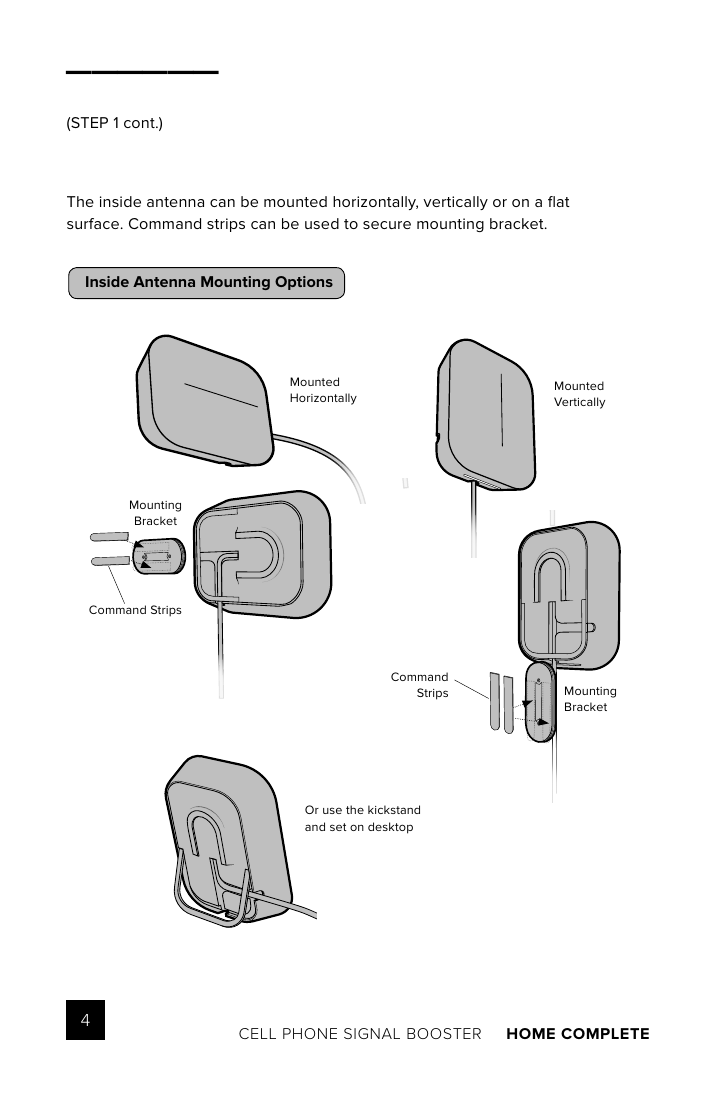
- Inside antenna & booster placement: Place the inside antenna where you need the greatest signal boost; place the booster at least 24" away from the inside antenna. Do not connect the booster to power until the system is fully installed. The inside antenna can be mounted horizontally, vertically, on a flat surface, or via the kickstand on a desktop.
- Mount & point the outside antenna toward the nearest cell tower — this is the most critical step and determines overall system performance. Pole mounting is preferred for easier direction adjustment (fascia/side-of-roof mounting is the alternative). The outside antenna must be at least 50 feet horizontal or 20 feet vertical from the inside antenna, with both antennas facing away from each other.
- Route & connect the outside antenna to the booster using the black 75 ft. coax cable, connected to the port labeled "OUTSIDE ANTENNA." All connections should be hand-tightened only.
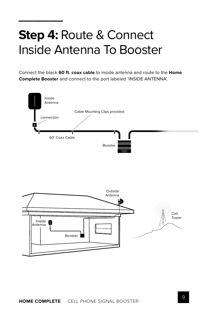
- Route & connect the inside antenna to the booster using the black 60 ft. coax cable, connected to the port labeled "INSIDE ANTENNA."
- Power up & optimize: Plug the power supply into a wall outlet (surge-protected power strip recommended), then connect to the booster. Rotate the outside antenna in 1/8-turn increments; after each turn, unplug/reconnect the booster to power while observing signal level on a cell phone near the inside antenna. Secure the outside antenna pointing in the direction giving the strongest signal.
Inside Antenna Mounting Options
Signal Routing Overview
Measuring Booster Performance
Note signal strength before and after installing the booster to confirm improvement.
| Signal | Excellent | Good | Fair | Poor | Dead Zone |
|---|---|---|---|---|---|
| 3G/1x | -70dBm | -71 to -85dBm | -86 to -100dBm | -101 to -109dBm | -110dBm |
| 4G/LTE | -90dBm | -91 to -105dBm | -106 to -110dBm | -111 to -119dBm | -120dBm |
A signal increase of just 3dB represents 2x the power and signal amplification.
Booster Light Patterns
- Solid Green: Booster is functioning properly, no installation issues.
- Blinking Green & Red: Band has reduced gain due to a feedback loop (oscillation) — a built-in safety feature to prevent interference with a nearby cell tower. No action needed if signal boost is already satisfactory.
- Solid Red: Band has shut off due to oscillation feedback loop — see Troubleshooting.
- Blinking Green & Yellow: Band has reduced gain (safety feature) — see Troubleshooting if boost is insufficient.
- Solid Yellow: Band has shut off due to overload from a nearby cell tower — outside antenna must be adjusted.
- Light Off: Verify the power supply has power.
Troubleshooting
Fixing Red Light Issues (Solid Red / Blinking Green-Red):
- Verify outside and inside antennas face away from each other; unplug and replug power.
- Verify the inside antenna is at least 24" from the booster and pointed away from it; unplug and replug power.
- Tighten all cable connections (hand-tighten only — no tools); redo the connection completely; unplug and replug power.
- Increase the distance (horizontally or vertically) between outside and inside antennas, adding cable if needed; unplug and replug power.
Fixing Yellow Light Issues (Solid Yellow / Blinking Green-Yellow): Outside antenna must be adjusted. Wait 10 seconds between adjustments, unplug/replug for lights to reset.
- Pole mount: Rotate the outside antenna away from the strongest cellular signal in 1/4-turn increments until the light turns green; unplug/replug power.
- Fascia mount: Move the outside antenna to a new location on the home/building; unplug/replug power, then secure in place.
Safety Guidelines
- Use only the power supply provided — a non-weBoost power supply may damage equipment.
- Designed for indoor, temperature-controlled use (below 100°F) — not for attics or similar hot locations.
- RF Safety: Any antenna used with this device must be located at least 8 inches from all persons.
- AWS Warning: Outside antenna must be installed no higher than 10 meters (31'9") above ground.
- This is a consumer device — you must register it with your wireless provider before use and have their consent.
- Must operate with approved antennas/cables only, installed at least 20cm (8 inches) from any person.
- Must cease operation immediately if requested by the FCC or your wireless provider.
- E911 location information may not be provided or may be inaccurate for calls served using this device.
- May be operated only in a fixed location for in-building use.
Registration links: T-Mobile/Sprint/MetroPCS, Verizon, AT&T (via attsignalbooster.com), UScellular.
Specifications
| Model Number | 460060 |
| FCC ID | PWO460060 |
| Connectors | F-Female |
| Antenna Impedance | 75 Ohms |
| Frequency Bands | 698-716 MHz, 729-746 MHz, 777-787 MHz, 824-894 MHz, 1850-1995 MHz, 1710-1755/2110-2155 MHz |
| Noise Figure | 5 dB nominal |
| Isolation | > 110 dB |
| Power Requirements | 5 VDC |
Each booster is individually tested and factory-set for FCC compliance and cannot be adjusted without factory reprogramming. If a detected signal is too high or an oscillation is detected, the booster automatically shuts off power on that band; it resumes normal operation after a minimum of 1 minute. After 5 automatic restarts, problematic bands are permanently shut off until the booster is manually restarted by removing power.
Warranty
2-year warranty against defects in workmanship and/or materials. Return directly to the reseller with dated proof of purchase, or to the manufacturer (at consumer's expense) with proof of purchase and an RMA number. Does not cover misuse, abuse, neglect, or mishandling. Replacement products may include recertified refurbished units.