
UCS Vega Synchro DC Chain Actuators — Installation & Maintenance Guide
Installation and maintenance guide for the UCS Synchro-Vega DC chain actuator, covering mounting brackets, wiring, and multi-actuator synchronization for automated windows and skylights.
Full text manual (for reference)
Installation and maintenance guide for the Functional Fenestration Inc. (FFI) Synchro-Vega DC Chain Actuator — a motorized chain-drive actuator for automating windows and skylights, including awning, hopper, wall/frame, and concealed-frame/curtain-wall applications.
Application Options
The Synchro-Vega mounts on a wall or window frame, and the chain operator attaches to the sash. Standard pivot brackets are included; optional brackets support hopper and wall mounting configurations. CAD files are available on request from FFI.
Specifications
- Supply voltage: 24 VDC ± 10%
- Normal current draw: 0.7 amps average (start-up current ~1.67 amps — size power supplies for at least 2× normal draw per actuator)
- Power cable: 3m, white, 2-conductor (± polarity inversion)
- Chain stroke length: 300mm (12 inches); chain speed: 9mm (0.354") per second
- Limit stop: electronic limit switch; Safety stop: electronic overload switch
- Typical switch: DPDT maintained contact (6 leads)
- Safety marks: ANSI/UL Recognized; CE; UL Recognized for UL projects
- Push/pull force: 55 lbs (250 N)
- Environment: 14° to 140°F (-10° to 60°C); max relative humidity 60%
- Control options: wall switch or CRM keypad; remote control and weather sensors (rain, wind, thermostat) can be added with a CRM
Parts Included
- 1 motor (actuator) with white cable
- 1 bag: 2 standard mounting brackets, 2 screws, 2 nuts
- 1 bag: 1 sash connector, 1 threaded sash connector pin, 2 screws (to connect to sash), 1 lock washer
Mounting Brackets
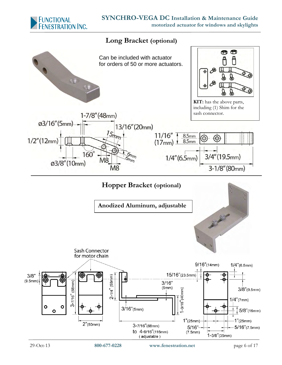
| Paint Color | Standard Bracket Pair (included) | Long Bracket Pair (sold separately) |
|---|---|---|
| Gray RAL 9006 | 40843F | 41455L |
| Black RAL 9005 | 40844G | 41456M |
| White RAL 9010 | 40845H | 41454K |
A Hopper Bracket (anodized aluminum, adjustable, part #41200C) is packaged individually and sold separately. Long brackets can be substituted for standard brackets at no extra cost on orders of 50+ actuators.
Critical Safety Notices
- Use only on windows/skylights out of reach of people — installation below 8 feet (2.5m) wall height is not recommended. If the sash is reachable, provide an emergency off-switch.
- Do not approach moving parts until they've come to a complete stop.
- Take precautions to avoid accidental closing of the window during install/uninstall to prevent injury (impact, squashing, cutting, or shearing).
- The actuator must be installed by skilled engineers and licensed electricians.
- Confirm window profiles/hinges can withstand the actuator's forces, sashes open/close freely with no obstacles, and the electrical system complies with local codes before installing.
- Turn the power circuit OFF before connecting the actuator.
- Do not tamper with actuators, or the warranty is void! Never open the actuator case, disassemble it, clip the wires, or attempt repair. For malfunctions, contact FFI Customer Service at 800-677-0228 or service@fenestration.net — FFI must inspect the motor for any defect claim.
- Actuator is for indoor use only. Operating range: 14° to 140°F (-10° to 60°C), max 60% relative humidity.
- Do not use more than one motor per vent unless using "Synchro-" series motors (designed for extra-wide vents) or two tandem non-Synchro motors connected to a 40733T Control Box.
Installation Steps
Top-Hinged Window with Windowsill or Skylights
- Mark the center-line of the sash and drill the holes.
- Fasten the Sash Connector to the sash with the supplied screws.
- Fasten the actuator to the window sill with Pivoting Brackets (recommended) or appropriate screws (not supplied). If the window is less than 35 inches tall, Pivoting Brackets must be used.
- Attach the chain operator to the sash with the Sash Connector Pin.
Top-Hinged Window with No Sill
- Mark the center-line of the sash and drill the holes.
- Fasten the Sash Connector with the supplied screws.
- Fasten the actuator to the wall just below the window with Pivoting Brackets.
- Attach the chain operator to the sash with the Sash Connector Pin.
Bottom-Hinged (Hopper) Windows
- Mark the center-line of the sash and drill the holes.
- Fasten the Sash Connector to the Hopper Bracket, and attach this assembly to the sash.
- Fasten the actuator to the window frame using the Standard Pivoting Brackets.
- Attach the chain operator to the sash with the Sash Connector Pin.
Bracket Mounting Diagrams
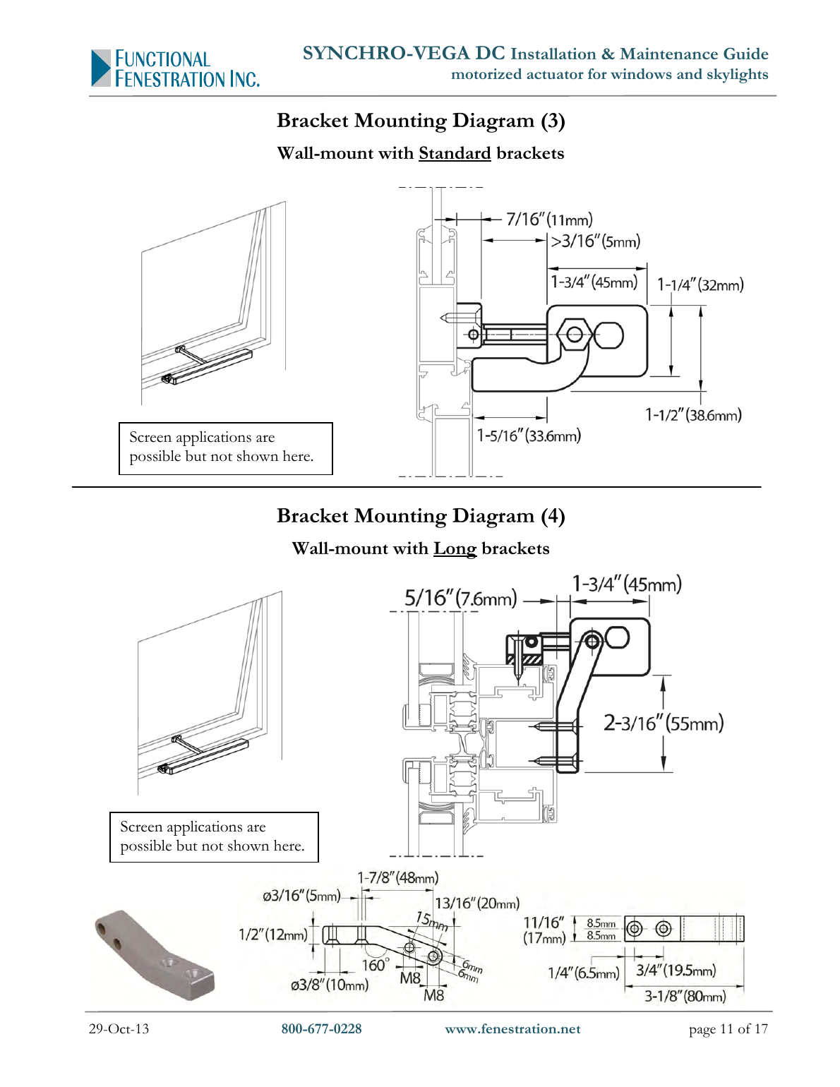
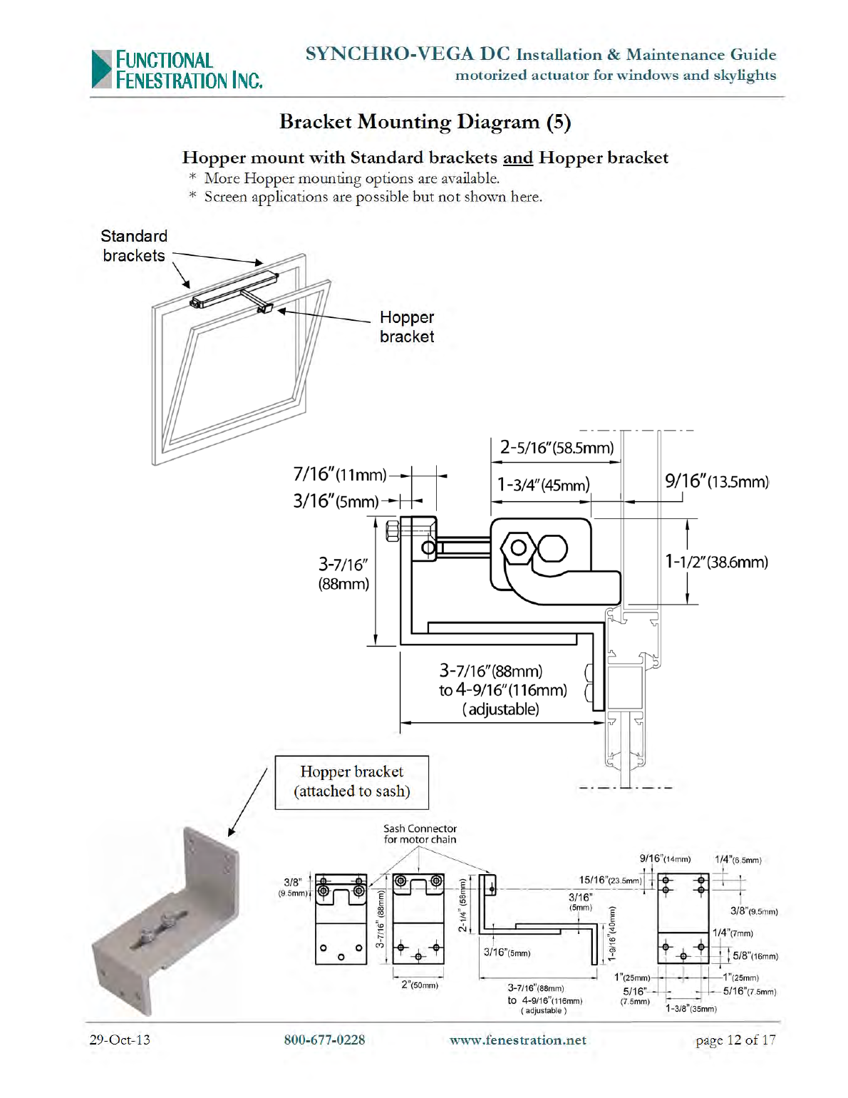
Note: Minimum sash height is 3× the chain length. Screen applications are possible but not shown in the diagrams.
Guidelines for Wiring & Power Supplies
- Voltage drop over wire distance is critical — plan for actual wire length, not straight-line distance, between power supply and actuator.
- Power supplies and wiring must handle both normal current draw and start-up amperage spikes (2–3× normal demand).
- FFI recommends sizing power supplies, controls, and conductors to provide 150%–250% of normal operating amperage — a momentary voltage drop below 24VDC ±10% can cause malfunction.
- Wiring terminations should use terminal blocks for positive connections.
- For multiple synchronized actuators on a single vent: the Gray, Black & White wires synchronize motors — only connect these between Synchro motors operating the same vent, per the wiring diagrams for 2, 3, or 4-actuator setups.
- For interfacing with DDC/BMS/BAS/HVAC or home automation systems, use a Control Relay Box (e.g. RB24) — this scheme is recommended for low-voltage systems because it cuts power to motors after a short time delay (<1 minute) per manufacturer recommendation.
- For simple wall-switch control, use a DPDT maintained-contact switch: press and hold up to open (until chain fully extends), press and hold down to close (until chain fully retracts).
Maintenance & Troubleshooting
- Do not approach moving parts until they've come to a complete stop.
- To open a window manually in case of power failure, remove the Sash Connector Pin.
- At least once a year, remove any debris accumulated where the chain emerges from the case, and check the power cable for signs of damage or wear.
- Prevent water or other liquids from entering the actuator.
- If experiencing problems, verify power is working, the switch is on, and there's no debris blocking the chain aperture.
- After installation, watch the actuator run a complete open/close cycle to confirm smooth, regular, and silent operation at full open/closed positions.
Warranty
Ultraflex Control Systems (UCS) products are guaranteed against defects in material and workmanship for two years from the date of manufacture. FFI honors this manufacturer's limited warranty for two years from the date of sale on FFI's invoice. Defective products must be returned freight-prepaid for repair or replacement at UCS's option.