
RISCO ShockTec 600S — Digital Shock Detector Installation Instructions
Installation instructions for the RISCO ShockTec 600S digital shock detector, providing bidirectional attack protection for indoor and outdoor use.
Full text manual (for reference)
Installation instructions for the RISCO ShockTec 600S — a digital shock detector providing bidirectional protection against attack, for indoor and outdoor use. This document is image-based (scanned); the diagrams below cover the full wiring and component layout, and the summary text below covers the essentials.
Overview
The ShockTec 600S uses a microprocessor to filter vibrations, distinguishing real intrusion attempts from background "false alarm" vibrations through an intelligent attack recognition system.
Main Features
- Digital microprocessor with intelligent signal processing
- LED that can be disabled to reduce power consumption during normal operation
- Selectable sensitivity level: Low / Medium / High
- Programmable to trigger alarm after a series of pulses
- Suitable for AC and DC power connections
- Auto-diagnostic feature and tamper protection
- LED indication for testing and diagnostic purposes
Wiring & Terminal Reference
See Figure 1 in the diagram below for the full terminal layout. Key terminals:
- LED — status indicator, enabled during installation
- Test — test button for diagnostic mode
- Sensitivity — adjustable dial (Low/Medium/High)
- Alarm — alarm output relay contact
- Tamper — anti-tamper switch contact
- Power — 9-16V DC / 9-16V AC power supply connections
Sensor Component Layout
| Item | Description |
|---|---|
| 1 | Micro switch (Tamper) |
| 2 | Circuit board |
| 3 | Piezoelectric sensor |
| 4 | Sensitivity adjustment |
| 5 | LED indicator |
| 6 | Terminal block |
| 7 | Mounting screws |
| 8 | Cover |
| 9 | Base plate |
Placing the Sensor
Position the sensor unit on the protected surface (safes, doors, windows) to maximize detection sensitivity while minimizing false alarms from environmental vibrations. See the diagram below for exact placement guidance and wiring connections (Figure 2).
Installation Reference Diagrams
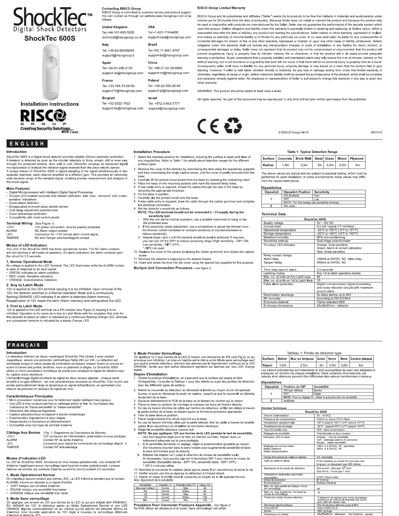
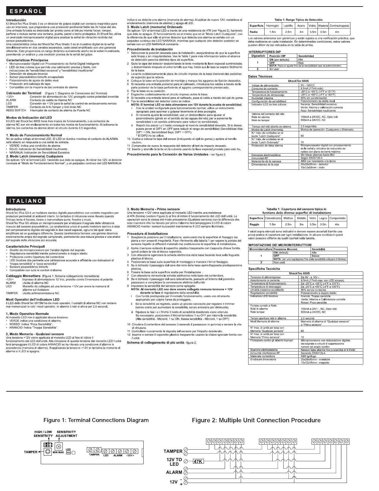
Multiple-Unit Interconnection
When monitoring multiple points on the same shipment/enclosure, several ShockTec 600S units can be interconnected via designated connectors:
- Identify the master unit and secondary (slave) units per the desired configuration.
- Connect the interconnection cables between units following the wiring diagram (Figure 2).
- Verify each unit is correctly labeled for later data identification.
- Activate the system and confirm all units respond in sync.
- Perform a final functional check before shipment.
LED Indication Modes
The LED behaves differently for each operational state — normal operation, alarm condition, tamper detection, low battery warning, and test mode (solid, flashing, or off patterns). See the wiring diagram above for the complete LED behavior table.
Technical Specifications
| Parameter | Specification |
|---|---|
| Power Supply | 9-16V DC / 9-16V AC |
| Current Consumption | 20mA (standby) |
| Operating Temperature | -10°C to +55°C |
| Relay Output | N.O./N.C. contact, 100mA max |
| Alarm Duration | 2 seconds (adjustable) |
| Tamper Switch | N.C. contact |
| Sensitivity Levels | Low / Medium / High (3 positions) |
| Dimensions | 65 x 45 x 25mm |
| Weight | 45g |
Warranty
Standard manufacturer warranty covering defects in materials and workmanship for the specified warranty period from date of purchase. Document reference: SI-Riso600Series-A0212.
Contact / Support
| Region | Phone | |
|---|---|---|
| Israel | +972-3-963-7777 | support@riscogroup.com |
| United Kingdom | +44-(0)-161-655-5500 | support@riscogroup.co.uk |
| USA | +1-631-719-4400 | support@riscogroup-usa.com |