
Makita Automatic Drapery Opener System — Information Guide
Information guide for the Makita Automatic Drapery Opener System (ZZCM101 Parent / ZZCM301 Kid motors).
Full text manual (for reference)
Information guide for the Makita Automatic Drapery Opener System — covering the "Parent" (ZZCM101) and "Kid" (ZZCM301) motors, control methods (IR remote, wall switch, timer, contact closure), address changes, and accessories.
Overview
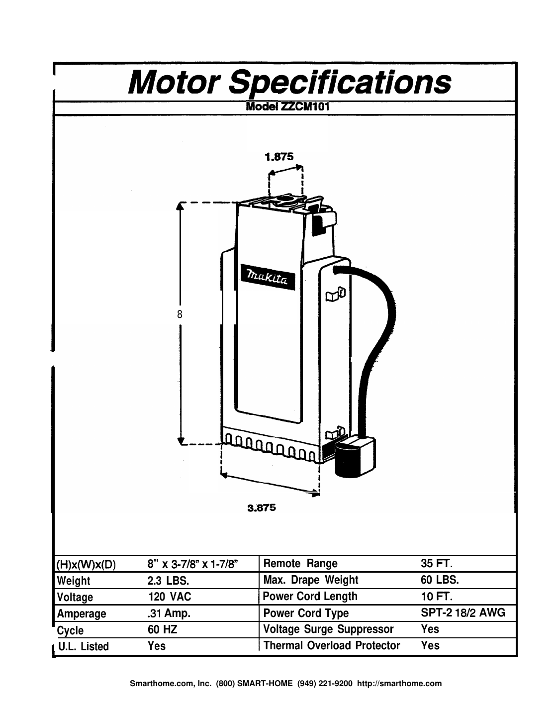
The Makita Automatic Drapery Opener System offers two motor types: the ZZCM101 "Parent" motor and the ZZCM301 "Kid" motor. Both motors are identical in power and design, but only the Parent contains the circuitry that receives and processes Open/Close/Stop commands. The Parent can control itself plus up to two Kid motors, which are connected via the supplied modular wire and cannot operate independently. Because Kid motors are lower cost than Parent motors, this design lowers overall system cost when multiple motors are used in one room.
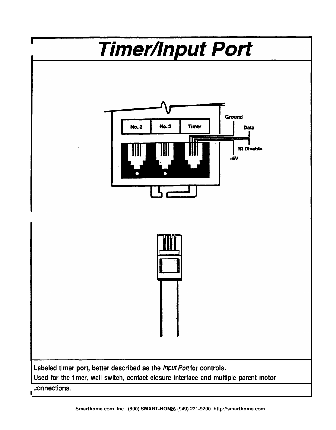
All Parent motors ship from the factory addressed to frequency 1, and can pass frequencies 2 and 3 through to attached Kid motor(s) via the Parent's "2" and "3" modular ports (the Parent also has a "Timer" port for accessories).
Key Facts
- Motor plugs directly into a standard 110V outlet — no electrician necessary — and clips directly to the rod
- 3-year warranty; UL listed per ANSI 325-1985, NEC/NFPA 70
- Tested over 30,000 openings and closings — equivalent to over 40 years of service at twice-daily operation
- Timer allows up to 4 opening/closing cycles daily for security, energy savings, and furniture protection
- Remote control operates up to 33 feet away
- Built-in thermal overload protector prevents overheating
- Clutch mechanism allows most draperies to be opened/closed manually
- Track speed: 50 feet per minute
- Infrared signal penetrates most draperies
- Handles up to a 40-foot window using a double-motor single-track configuration
- Supports one-way (left or right), center, multiple, and reverse operation configurations
- Each motor is rated for 60 lb. of drapery over a 20 ft. span; using two motors on a single track doubles the rating
- Designed for pinch pleat drapery; installs the same as a manual traverse rod
Methods of Control
The Makita motors can be controlled via infrared remote, wall switch, timer, or Contact Closure Interface (CCI) — or by emulating the serial data stream directly.
Infrared Remote Control
There are four remote control models; the number after "ZZRC" denotes how many motors it controls (e.g., ZZRC30 controls 3 motors). While motors accept all ten frequency signals, remotes are limited to sending frequencies 1–6, so a maximum of six motors can be independently controlled via remote per room (IR does not penetrate walls, so addresses can be reused in other rooms).
Wall Switch
The wall switch sends the same type of serial data as the remote, but is limited to addresses/frequencies 1–3 (maximum 3 motors per switch). It is low voltage (5V), comes with 25 ft. of wire that connects to the Parent motor through the Timer port, and can be recess- or surface-mounted using the supplied sub-base. Naming follows the same convention as remotes (e.g., ZZWS30 controls 3 motors).
Timer
The timer can be set for up to four opening/closing cycles per day. It sends all ten frequencies in sequence, controlling any motor(s) attached to it regardless of address. It is low voltage and plugs directly into the motor via low-voltage modular phone-type wire.
Contact Closure Interface (CCI)
The CCI allows motor operation through dry contacts, converting simple contact closures into the serial data the motor requires. It handles momentary or maintained switch inputs, and includes home-theater masking and multiple preset stop-point capabilities. Inputs use 16 AWG or smaller wire; output is a direct connection to the motor's Timer port using 26 AWG phone-type wire with RJ modular plugs. The CCI is not designed for direct connection to a Kid motor (ZZCM301) — doing so can damage the CCI.
The CCI can send all ten frequencies (including an "all" mode for simultaneous operation of all connected motors) and supports four switch modes selected via mode dip switches: Momentary, Maintained, Theater (aspect-ratio masking), and Multiple Presets (specific stop points on the track). Any programmable serial-data or dry-contact-relay control system can integrate with the Makita motors through the CCI.
Address Changes
All CM101 (Parent) motors ship from the factory set to address 1 and respond to Open/Close/Stop commands on frequency 1, while also accepting and passing on frequencies 2 and 3 to attached Kid motor(s). Parent motors can be altered to accept commands for up to 10 different frequencies — the highest Parent address is #8, with its attached Kids automatically becoming #9 and #10.
An unlimited number of motors can be independently controlled by hardwiring multiple CCIs or Wall Switches (each CCI handles up to 10 motors per control station; each Wall Switch handles up to 3). The IR remote is limited to 6 addresses per room, though addresses can be duplicated in other rooms.
Example: To independently control two motorized draperies on two separate windows in the same room (4 motors total), leaving factory defaults would result in both Parents responding to #1 and both Kids to #2. Changing one Parent to address #3 makes its Kid automatically #4, giving independent control of all four motors — this configuration would require a ZZRC60 remote to operate all motors.
How to Change a Parent Motor's Address
To alter a Parent motor's (ZZCM101) address, one or more connections on the Central Processing Board (CPU) must be cut. Only the Parent motor's address needs to be changed — the Kid motor(s) automatically respond to the next higher address.
- Lay the motor on its side on a flat surface and remove the bottom slide cover. Open the motor by removing all screws and lifting the encasement off. Hint: as you remove the top half of the housing, hold the spring-loaded locking device at the top of the motor in place to avoid having to reinstall and pre-load the spring.
- Locate the Central Processing Board.
- Carefully lift the board (as far as the wires allow) to give room to work.
- Locate the connection(s) that need to be cut, using the address/connections reference chart included in the manual (0 = leave connection intact, X = cut connection).
- Using a razor blade or Exacto knife, carefully cut the connection(s) between the terminals for the desired address. Make multiple passes to ensure the connection is fully broken, being careful not to slip and cut other connections.
- Reposition the processing board in the lower half of the case and replace the cover, making sure all wires are clear of the encasement and the female modular ports are fitted into their key way for a clean fit.
- Screw the case back together carefully — the screws are self-tapping and can strip if over-tightened.
- Test the change using the remote control.
Binary Codes (Serial Data Protocol)
The ZZCM101 Parent motor is controlled by signals sent as 10-bit serial data streams with no leader codes (a characteristic unique to Makita). Timing parameters:
- First Pulse Time = 248μs
- Length = 21 mS
- Carrier = 40 KHz
- Repeat Count = Continuous
- "0" = 1 millisecond, "1" = 2 milliseconds
Data stream configurations exist for all 10 frequencies (Open/Close/Stop); the Stop command is always the same regardless of Open or Close direction.
Accessories
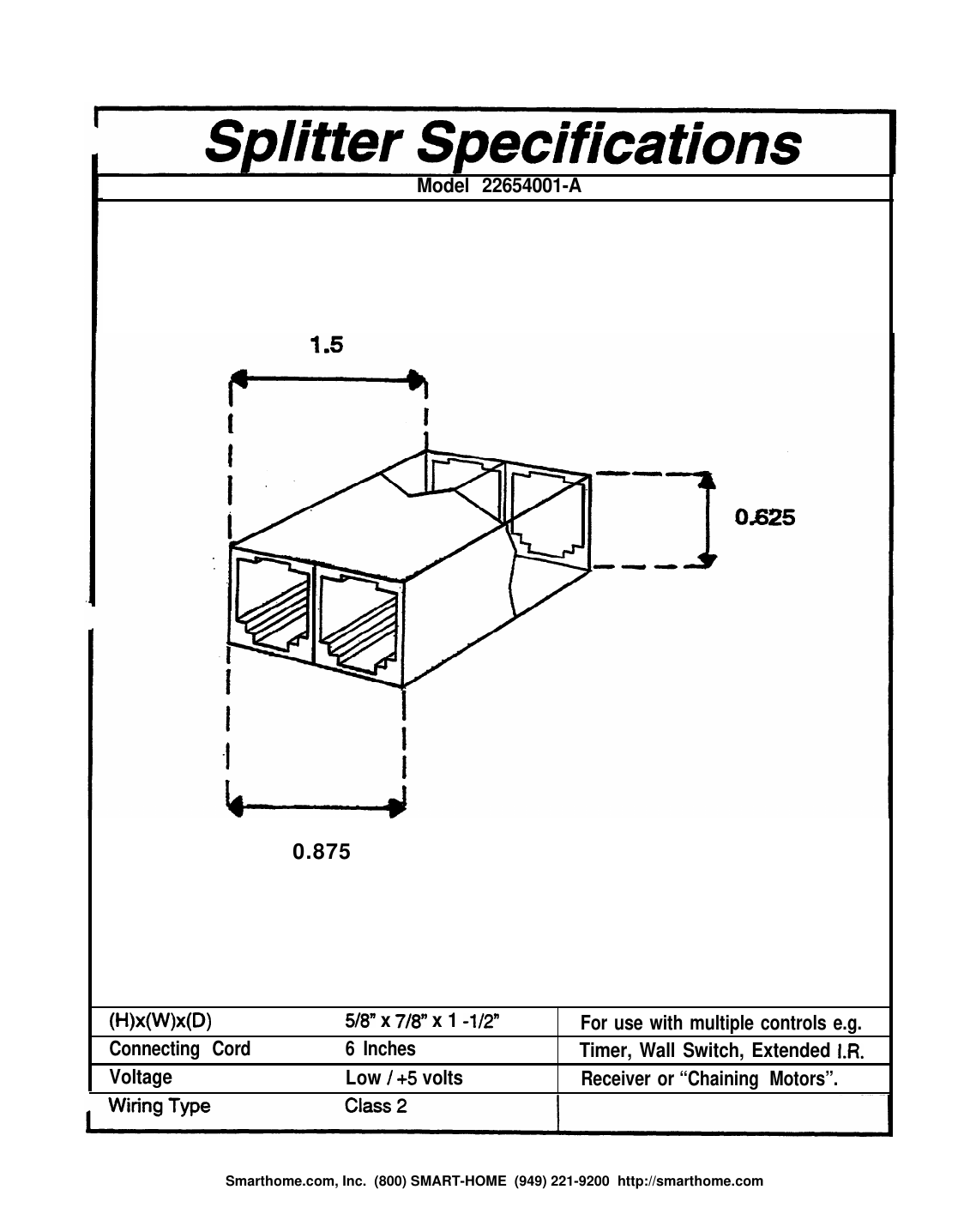
All accessories in this section plug into the "Timer" port of the Parent motor (more accurately described as an "Input" port). When using more than one accessory at once, the Splitter (22654001-A) is required.
- Extended IR Receiving Eye — for cases where the Parent motor's built-in IR receiver is hidden behind a wall, cornice box, or valance. Available in 5 ft. (Model 22631101-A) and 10 ft. (Model 22631102-A) lead lengths; mounts anywhere in the room using supplied Velcro.
- Splitter (22654001-A) — allows multiple accessories (timer, wall switch, extended IR eye) to be connected to a single Parent motor's Timer/Input port simultaneously.
- Modular Connecting Wires — low-voltage phone-type wire for linking motors, accessories, and the splitter.
Reference Diagrams
Support
Smarthome.com, Inc. · (800) SMART-HOME · (949) 221-9200 · smarthome.com