
LockState RemoteLOCK 7i (LS-7i) WiFi Keypad Deadbolt — Installation & Programming Guide
Illustrated installation guide for the LockState RemoteLOCK 7i (LS-7i) WiFi-enabled keypad deadbolt lock, including keypad programming codes.
Full text manual (for reference)
Quick reference guide for the LockState RemoteLOCK 7i (LS-7i) — a WiFi-enabled keypad deadbolt lock. This manual is presented as an illustrated installation poster; the images below and the full downloadable PDF cover the complete step-by-step install. This page summarizes the installation sequence, keypad programming codes, and factory defaults for quick reference.
Installation Reference
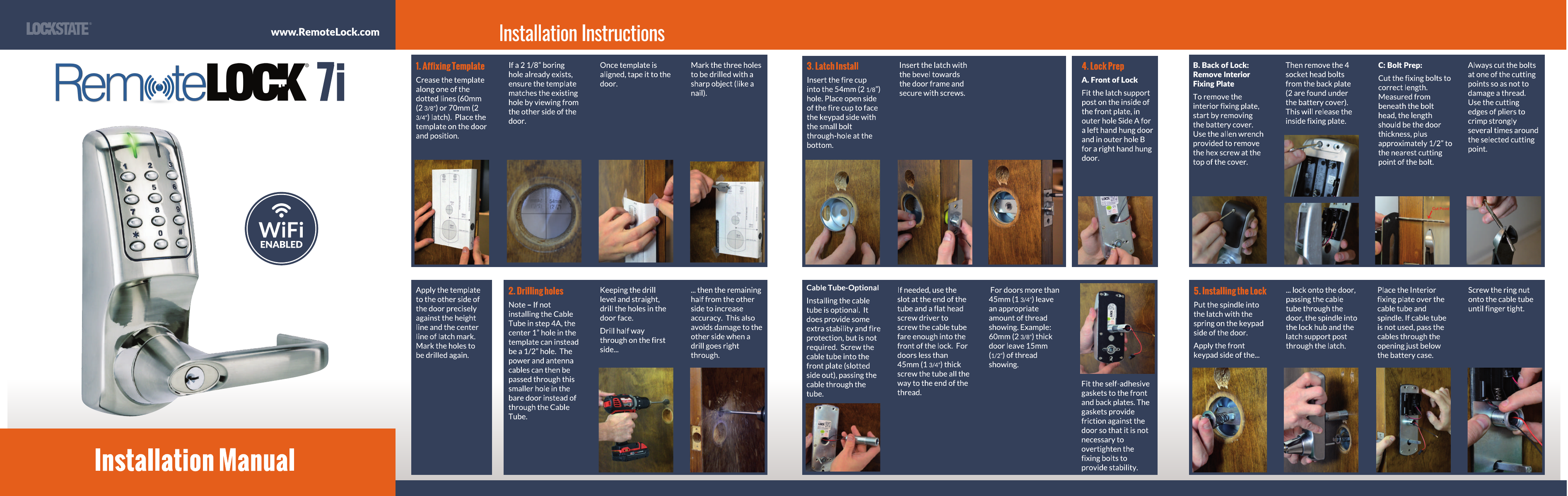
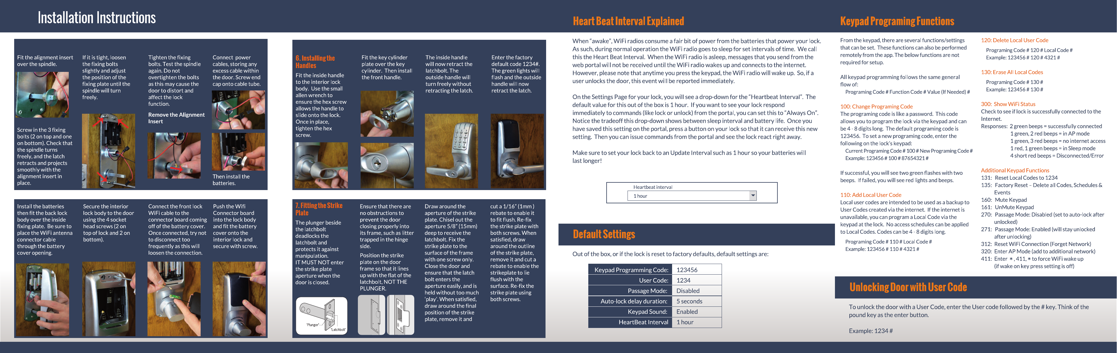
Installation Overview
Full illustrated steps are in the downloadable PDF. High-level sequence:
- Crease and affix the paper template to both sides of the door, aligned with the existing bore hole (or center height marks for new installs).
- Drill holes halfway through from each side of the door for the most accurate, cleanest result.
- Install the latch: insert the fire cup into the 2⅛" (54mm) hole with the open side facing the keypad side, then insert the latch with the bevel toward the door frame and secure with screws.
- Optionally install the Cable Tube for added stability and fire protection (not required — power/antenna cables can pass through a smaller ½" hole instead).
- Prepare the lock: fit the latch support post inside the front plate, remove the interior fixing plate from the back of the lock, and cut the fixing bolts to the correct length for your door thickness.
- Install the lock: fit self-adhesive gaskets, pass the spindle through the latch, mount the front keypad side, and secure the interior fixing plate with the ring nut.
- Install the handles: fit the alignment insert over the spindle, secure the fixing bolts, install batteries, connect the WiFi antenna cable, then remove the alignment insert and fit the inside/outside handles.
- Enter the factory default code 1234# to confirm operation — the outside handle will retract the latch on a valid code.
- Fit the strike plate: align with the flat of the latchbolt (not the plunger), chisel a 5/8" (15mm) deep aperture, cut a 1/16" (1mm) rebate for a flush fit, then secure with both screws.
WiFi Heartbeat Interval
The WiFi radio consumes significant battery power when awake. During normal operation, the radio sleeps at a set interval to conserve battery — this is the "Heartbeat Interval," the frequency at which the lock checks in with the web portal (default: 1 hour). Portal commands aren't received until the next heartbeat unless "Always On" is selected. Pressing the keypad wakes the WiFi radio immediately, so lock/unlock events are always reported right away regardless of this setting. Shorter intervals mean faster remote response but reduced battery life — remember to set the interval back to normal (e.g. 1 hour) after testing to preserve battery life.
Default Settings
| Keypad Programming Code | 123456 |
| User Code | 1234 |
| Passage Mode | Disabled |
| Auto-lock Delay Duration | 5 seconds |
| Keypad Sound | Enabled |
| HeartBeat Interval | 1 hour |
Keypad Programming Functions
General format: Programming Code # Function Code # Value (if needed) #
| Code | Function | Example |
|---|---|---|
| 100 | Change Programming Code (4-8 digits, default 123456) | 123456 # 100 # 87654321 # |
| 110 | Add Local User Code (backup to codes created online; no schedules apply) | 123456 # 110 # 4321 # |
| 120 | Delete Local User Code | 123456 # 120 # 4321 # |
| 130 | Erase All Local Codes | 123456 # 130 # |
| 131 | Reset Local Codes to 1234 | — |
| 135 | Factory Reset — deletes all codes, schedules & events | — |
| 160 / 161 | Mute / Unmute Keypad | — |
| 270 / 271 | Passage Mode: Disabled (auto-lock) / Enabled (stays unlocked) | — |
| 300 | Show WiFi Status (see beep codes below) | — |
| 312 | Reset WiFi Connection (forget network) | — |
| 320 | Enter AP Mode (add additional network) | — |
| 411 | Force WiFi wake up (if "wake on key press" is off) | * 411 * |
WiFi Status Response Codes (Function 300)
- 2 green beeps — successfully connected
- 1 green, 2 red beeps — in AP mode
- 1 green, 3 red beeps — no internet access
- 1 red, 1 green beep — in Sleep mode
- 4 short red beeps — disconnected / error
General success/failure indicators: success shows two green flashes with two beeps; failure shows red lights and beeps.
Unlocking the Door with a User Code
Enter the user code followed by the # key (think of # as "enter"). Example: 1234 #.