
Linear DXR-701 Single-Channel Digital Receiver — Installation Instructions
Installation instructions for the Linear DXR-701 single-channel digital receiver.
Full text manual (for reference)
Installation instructions for the Linear DXR-701 single-channel digital receiver, used for gate/door access control and remote-controlled devices.
Overview
The DXR-701 is a digital receiver with an isolated relay output, designed for Linear's DX Format transmitters. It uses a digital DX code with over one million possible codes; transmitters are precoded at the factory (no field coding required). Receiver memory holds up to 32 transmitters and is retained even without power.
- Power: 11-17 VDC or 12-16 VAC
- Relay rating: N.O./N.C. contacts switch up to 1 amp at 24V AC/DC
- Antenna: 9-inch wire lead, included
- Program Indicator: Red LED — lights as transmitters are received, blinks to indicate interference
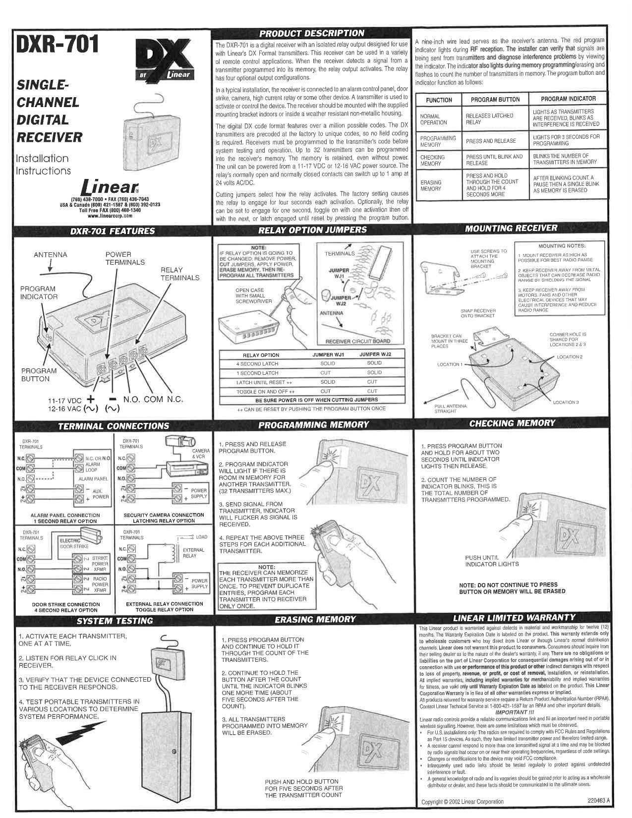
Program Button & Indicator Functions
| Function | Program Button | Program Indicator |
|---|---|---|
| Normal Operation | Releases latched relay | Lights as transmitters received; blinks with interference |
| Programming Memory | Press and release | Lights 3 seconds for programming |
| Checking Memory | Press until blink, then release | Blinks number of transmitters in memory |
| Erasing Memory | Press/hold through the count, hold 4 more seconds | Blinks count, pause, then single blink when erased |
Relay Option Jumpers
Jumpers WJ1 and WJ2 are located on the receiver circuit board near the antenna/terminals. Always power off before cutting jumpers.
| Relay Option | Jumper WJ1 | Jumper WJ2 |
|---|---|---|
| 4 Second Latch | Solid | Solid |
| 1 Second Latch | Cut | Solid |
| Latch Until Reset** | Solid | Cut |
| Toggle On and Off** | Cut | Cut |
**Can be reset by pushing the program button once. If changing the relay option: remove power, cut the jumpers, apply power, erase memory, then reprogram all transmitters.
Mounting
- Mount the receiver as high as possible for best radio range.
- Keep away from metal objects that can shield the signal.
- Keep away from motors, fans, and other electrical devices that cause interference.
- Attach the mounting bracket with screws; the receiver snaps onto the bracket. Pull the antenna straight. The bracket can mount in three positions (a corner hole is shared between positions 2 and 3).
Wiring Configurations (see diagram above)
- Alarm Panel Connection (1 Second Relay Option): N.C./N.O./COM wired to the alarm loop, with aux power supplied from the alarm panel.
- Security Camera Connection (Latching Relay Option): N.C./COM/N.O. wired to a camera and VCR, with its own power supply.
- Door Strike Connection (4 Second Relay Option): N.C./COM/N.O. wired to an electric door strike, with a separate strike power transformer and radio power transformer.
- External Relay Connection: N.C./COM/N.O. wired to an external relay with a load and power supply.
Programming Memory
- Press and release the program button.
- The program indicator lights if there is room for another transmitter (32 max).
- Send a signal from the transmitter — the indicator flickers when the signal is received.
- Repeat for each additional transmitter.
Note: the receiver can memorize a transmitter multiple times. Program each transmitter only once to avoid duplicate entries filling memory.
Checking Memory
- Press and hold the program button for about 2 seconds until the indicator lights, then release.
- Count the indicator blinks — this equals the total number of transmitters programmed.
Note: do not continue holding the button past this point or memory will be erased.
Erasing Memory
- Press and hold the program button through the blink count of programmed transmitters.
- Continue holding until the indicator blinks once more (about 5 seconds after the count finishes).
- All transmitters in memory are erased.
System Testing
- Activate each transmitter one at a time.
- Listen for the relay click in the receiver.
- Verify the connected device responds correctly.
- Test portable transmitters from various locations to determine real-world performance.
Regulatory & Warranty Notes
- U.S. installations comply with FCC Part 15 (limited power and range). Unauthorized modifications may void FCC compliance.
- The receiver cannot process multiple signals simultaneously and may be blocked by other RF signals on the same frequency — test wireless links regularly for interference.
- Linear Limited Warranty: 12 months against defects in material/workmanship. Applies only to wholesale customers who buy direct from Linear or authorized distributors. Returns require a Return Product Authorization Number (RPA#) — call 1-800-421-1587.
Linear Corporation • (760) 438-7000 • USA/Canada: (800) 421-1587 / (800) 392-0123 • www.linearcorp.com