
Linear D-67 / D-67L / D-67F / D-UR / DX-12 Digital Receivers — Installation Instructions
Installation and reference sheet for the Linear single-channel digital receivers (D-67, D-67L, D-67F, D-UR, DX-12), covering code switch setup, wiring to alarm control panels, antenna connection, and mounting.
Full text manual (for reference)
Installation and reference sheet for the Linear single-channel digital receivers: models D-67 (standard), D-67L (latching), D-67F (toggling), D-UR (6-volt), and DX-12 (shielded, external antenna). These receivers are used in wireless security systems and remote-control applications, typically connected to a hardwired alarm control panel to add wireless remote capability.
Model Overview
- D-67 — Standard receiver; output triggers for four seconds when activated.
- D-67L — Latching receiver; output latches when activated until manually reset.
- D-67F — Toggling receiver; output alternately latches and unlatches when activated.
- D-UR — 6-volt receiver; output triggers for four seconds when activated.
- DX-12 — Shielded receiver, same as the D-67 but in a metal case with an external antenna input for a Model EXA-1000 or EXA-2000 remote antenna.
Setting the Security Code
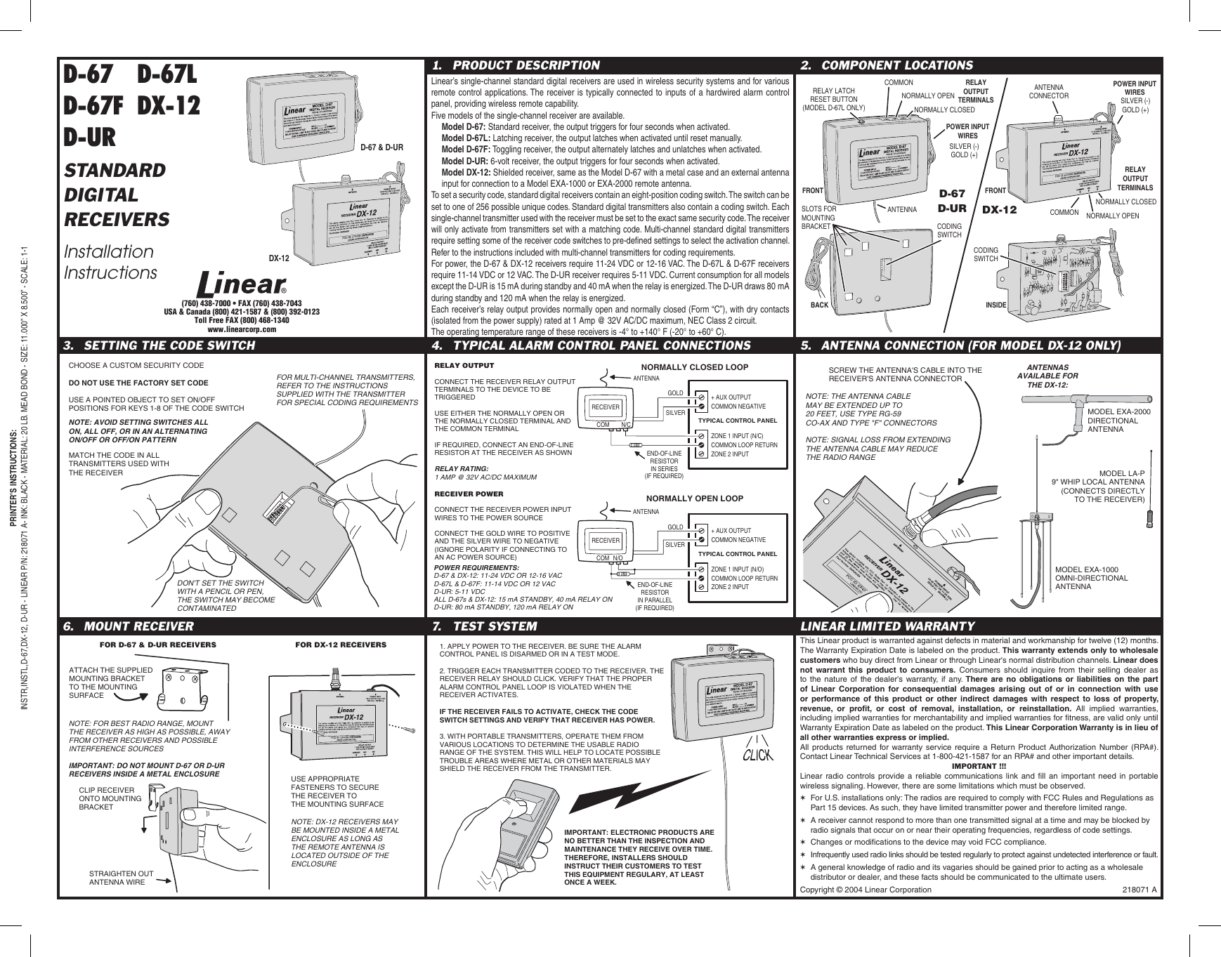
Standard digital receivers contain an eight-position coding switch, settable to one of 256 possible unique codes. Every single-channel transmitter used with the receiver must be set to the exact same security code — the receiver only activates from transmitters with a matching code. Multi-channel standard digital transmitters require setting some of the receiver's code switches to pre-defined positions to select the activation channel (refer to the transmitter's instructions).
Important: Do not use the factory-set code. Use a pointed object (not a pencil or pen — graphite/ink can contaminate the switch) to set the on/off positions. Avoid setting all switches on, all off, or in an alternating on/off pattern.
Power Requirements
| Model | Power Input | Current Draw |
|---|---|---|
| D-67 & DX-12 | 11–24 VDC or 12–16 VAC | 15 mA standby, 40 mA relay on |
| D-67L & D-67F | 11–14 VDC or 12 VAC | 15 mA standby, 40 mA relay on |
| D-UR | 5–11 VDC | 80 mA standby, 120 mA relay on |
Each receiver's relay output provides normally open and normally closed (Form "C") dry contacts, isolated from the power supply, rated at 1 Amp @ 32V AC/DC maximum, NEC Class 2 circuit. Operating temperature range: -4° to +140° F (-20° to +60° C).
Alarm Control Panel Connections
Connect the receiver's relay output terminals to the device to be triggered, using either the normally open or normally closed terminal along with the common terminal. If required, connect an end-of-line resistor at the receiver as shown in the wiring diagram (in series for a normally closed loop, in parallel for a normally open loop). For receiver power, connect the gold wire to positive and the silver wire to negative (polarity may be ignored if connecting to an AC power source).
Antenna Connection (DX-12 Only)
Screw the antenna's cable into the receiver's antenna connector. The antenna cable may be extended up to 20 feet using Type RG-59 co-ax cable and Type "F" connectors — note that extending the cable may reduce the radio range. Compatible antennas include the Model EXA-2000 directional antenna, Model EXA-1000 omni-directional antenna, and the Model LA-P 9" whip local antenna (connects directly to the receiver).
Mounting
- For D-67 & D-UR receivers: clip the receiver onto the supplied mounting bracket, then attach the bracket to the mounting surface using appropriate fasteners.
- For DX-12 receivers: straighten out the antenna wire before mounting; DX-12 receivers may be mounted inside a metal enclosure as long as the remote antenna is located outside the enclosure.
- Important: Do NOT mount D-67 or D-UR receivers inside a metal enclosure.
- For best radio range, mount the receiver as high as possible, away from other receivers and possible interference sources.
Testing the System
- Apply power to the receiver. Be sure the alarm control panel is disarmed or in test mode.
- Trigger each transmitter coded to the receiver. The receiver relay should click. Verify that the proper alarm control panel loop is violated when the receiver activates.
- If the receiver fails to activate, check the code switch settings and verify that the receiver has power.
- With portable transmitters, operate them from various locations to determine the usable radio range of the system. This helps locate possible trouble areas where metal or other materials may shield the receiver from the transmitter.
Reference Diagram
Important Notes on Radio Controls
- For U.S. installations: these radios comply with FCC Rules and Regulations as Part 15 devices, and therefore have limited transmitter power and limited range.
- A receiver cannot respond to more than one transmitted signal at a time and may be blocked by radio signals occurring on or near its operating frequencies, regardless of code settings.
- Changes or modifications to the device may void FCC compliance.
- Infrequently used radio links should be tested regularly to protect against undetected interference or fault. Installers should instruct customers to test this equipment regularly, at least once a week.
Warranty
This Linear product is warranted against defects in material and workmanship for twelve (12) months from the Warranty Expiration Date labeled on the product. This warranty extends only to wholesale customers who buy direct from Linear or through Linear's normal distribution channels; Linear does not warrant this product to consumers (consumers should inquire with their selling dealer). All products returned for warranty service require a Return Product Authorization Number (RPA#) — contact Linear Technical Services at 1-800-421-1587.