
IST V500 (Slave) Video Monitor — Operation Instructions
Operation instructions for the Intrasonic V500 (Slave) Video Monitor, an indoor intercom monitor that must be paired with a Master monitor — it does not work as a standalone master.
Full text manual (for reference)
Operation instructions for the Intrasonic V500 (Slave) Video Monitor — an indoor intercom monitor that connects to a Master video monitor unit. Note: this unit does not work as a standalone master; it must be paired with a Master monitor to operate.
Specifications
| Display screen | 7" TFT LCD screen |
| Definition | 800(H) x 480(V) |
| Standard | PAL/NTSC |
| Calling mode | Two-way conversation |
| Calling time | 120 seconds |
| Standby current | Maximum 200mA |
| Work current | Maximum 500mA |
| Power supply | Built-in (AC 100V~240V) or external switching supply (DC12V) — both optional, check actual model |
| Work temperature | -10°C to +60°C |
| Installation | Surface mounting |
| Extension memory | SD card, maximum 32GB (Class 10 or higher) |
| Picture format | JPEG standard |
Box Contents
- Indoor monitor — 1 pc
- Screw anchors — 4 pcs
- Wall screws — 4 pcs
- Bracket — 1 pc
- 4-pin line — 6 pcs
- 2-pin line — 1 pc
- User manual — 1 pc
- External switching power supply DC 12V (optional, check actual model) — 1 pc
Wiring Notes
The electric lock, power source, and camera are not included in the package — purchase an electric lock suitable for your needs. A standard relay mechanism supports locks with Normally Open (N.O.) door-unlocking methods: in the normal state the dry contact is open, keeping the lock closed. Pressing the unlocking push-button closes the dry contact and releases the lock.
The indoor monitor may have a built-in power supply (wide voltage range AC 100V~240V) or use an external switching power supply — check with the manufacturer. Pull out the AC power plug before installing the device. Note the silk-printed labels on the PCB to avoid incorrect wiring.
Cable requirement: use 4-conductor (4C) ordinary non-STP wiring cable. Maximum effective distance from the outdoor camera to the furthest indoor monitor:
- ≤28m using 4x0.2mm² cable
- ≤50m using 4x0.3mm² cable
- ≤80m using 4x0.5mm² cable
Wiring Diagrams
Important: when connecting a Slave unit like the V500, it must be activated as "Slave" in the monitor's mode settings before use — see Operation Introduction below.
Setting the Monitor Mode (Master/Slave)
On the main menu, go to Mode. Set Mode to "Master" (the unit connects to outdoor cameras/door stations) or "Slave" (the unit connects to the main/sub indoor unit). Additional Mode settings include:
- Door2 status — enable or disable Door2 preview
- Record mode — "Record" (auto-records when a visitor presses the outdoor call button, SD card models only) or "Snapshot" (captures a still frame instead)
- Door1/Door2 unlock time — adjustable from 2 to 10 seconds
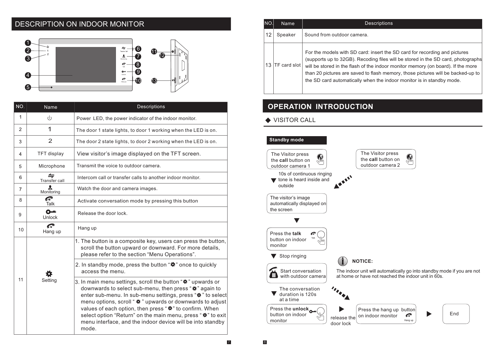
Operation — Visitor Call Flow
- A visitor presses the call button on outdoor camera 1 or 2.
- 10 seconds of continuous ringing tone sounds inside and outside; the visitor's image displays automatically on the screen.
- Press the Talk button on the indoor monitor to stop ringing and start a conversation with the outdoor camera (conversation duration: 120 seconds at a time).
- Press Unlock to release the door lock, or press Hang up to end the call and return to standby.
Both the visitor's voice and image continue displaying for 20 seconds after the door has been unlocked, to confirm successful entry.
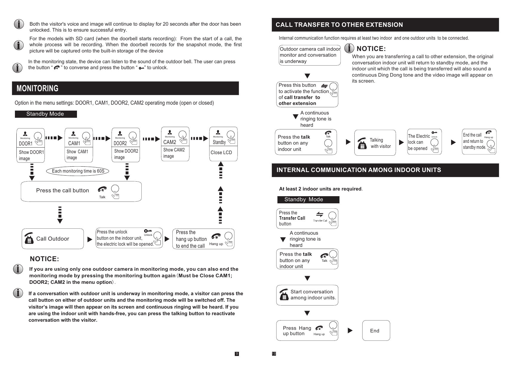
Internal Communication Between Indoor Units
Requires at least 2 indoor units. From standby mode, press Transfer Call on one indoor unit — a continuous ringing tone sounds on the other units. Press Talk on any indoor unit to start a conversation between indoor units; press Hang up to end the call.
Menu Settings Reference
System
- Language — change the on-screen display language.
- Time — set system date/time; date format options: YY-MM-DD, DD-MM-YY, MM-DD-YY.
- Information — view software version and release date.
- Format SD / Format flash — format the SD card or built-in storage (SD card must be Class 10 or higher).
- Backup pictures — copy photos from built-in storage to SD card (SD card models; originals are deleted after backup).
- Update — upgrade firmware via SD card (do not remove the SD card or power off during the update).
- Reboot — restart the unit.
Ring
- Ring select — choose the doorbell tone for Door1 and Door2 (12 tones each).
- Ring volume — set volume (00-10) for three different time periods of the day (e.g. 06:00-12:00, 12:00-18:00, 18:00-06:00); vibrate/ring duration adjustable 10s-45s.
Alarm
- CAM1/CAM2 sensor type — NO (Normally Open: alarm triggers when voltage changes low→high), NC (Normally Closed: alarm triggers when voltage changes high→low), or Disable.
- CAM1/CAM2 — enable/disable camera preview.
- CAM1/CAM2 ring time — alarm ring duration when triggered, 0-30 seconds.
- Alarm record — "Record" or "Snapshot" when an alarm triggers.
Color
Adjust brightness (0-50, default 25), contrast (0-50, default 25), and chroma (0-50, default 35) per Door1/Door2/CAM1/CAM2 channel.
Files (Playback)
SD card models only. "Record files" and "Snapshot files" lists let you select and Play, Delete current file, or Delete all files.
Alarm Function & Connection
Each camera (CAM1, CAM2) has an alarm function — when the trigger terminal and GND are shorted, the alarm activates, the indoor unit's speaker rings continuously for 120 seconds, and (SD card models) recording/snapshot starts per the system settings. Press Hang up to stop alarming and return to standby.
The alarm connection supports 2 normally-closed (NC) or normally-open (NO) inputs per camera channel, without limitation on input type. Connect the alarm detector's ALM terminal in parallel with the camera's ALM terminal, and the detector's ground terminal in parallel with the camera's GND terminal (the alarm detector must be supplied by its own external power source). For NO inputs, shorting GND and ALM triggers the alarm; for NC inputs, opening the GND-ALM connection triggers the alarm.
Returns & Warranty
Product returns require a Return Merchandise Authorization (RMA) number — call customer service at 877-435-0670 before returning any merchandise. Unauthorized returns are subject to refusal. Return-to-stock items must be in unopened original boxes and like-new condition; a 10% restocking charge applies to all returns.
Intrasonic Technology warrants its products against manufacturing defects for 2 years from closing/actual installation. This warranty applies only to products purchased from authorized dealers/distributors, and extends to the original or subsequent owner during the warranty term. Intrasonic will repair or replace defective products at its discretion, at no charge, with a reconditioned or new product. Contact 877-435-0670 for an RMA before attempting to dismantle any product — dismantling voids the warranty.