
IST I600 — In-Wall Stereo & Intercom System Installation Manual
Installation manual for the IST I600 in-wall stereo/intercom system — power, antenna, speaker, amplifier, and mounting wiring.
Full text manual (for reference)
Installation manual for the IST (Intrasonic Technology) I600 In-Wall Stereo/Intercom System — covering power, antenna, speaker, amplifier, volume control, and auxiliary input wiring, plus wall mounting.
Important Safety Instructions
- Read and keep these instructions; heed all warnings.
- Do not use this apparatus near water; clean only with a dry cloth.
- Do not block ventilation openings; do not install near heat sources (radiators, stoves, amplifiers, etc.).
- Do not defeat the safety purpose of a polarized or grounding-type plug.
- Protect the power cord from being walked on or pinched.
- Unplug during lightning storms or extended periods of disuse.
- Refer all servicing to qualified personnel — do not open the unit or attempt repairs yourself.
- Do not expose the apparatus to rain, moisture, dripping, or splashing; keep liquid-filled objects (vases, etc.) off the unit.
- The unit should be connected to a mains socket with a protective earthing (ground) connection.
- Do not expose the battery to excessive heat (sunshine, fire, etc.).
Connecting the Power
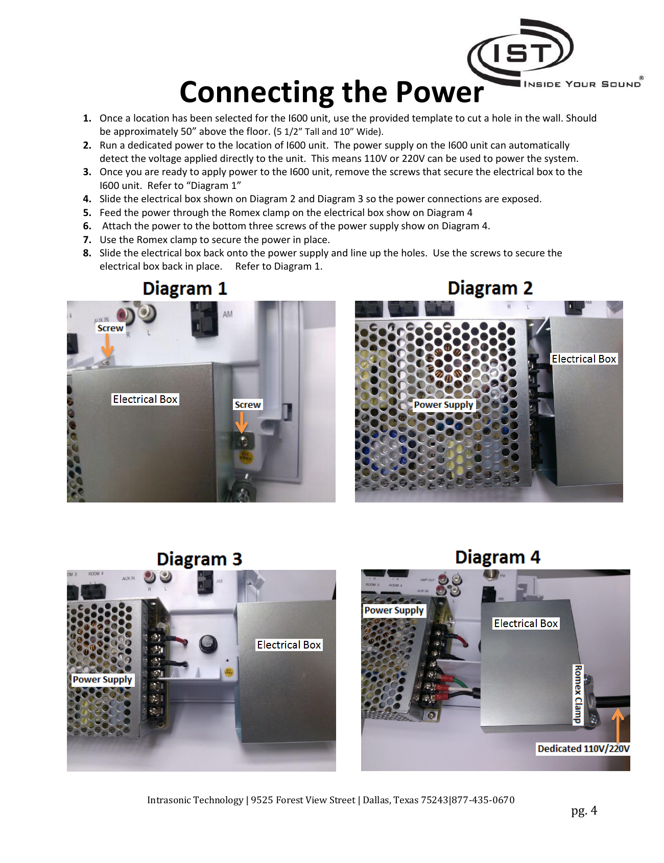
- Select a mounting location — approximately 50" above the floor — and use the provided template to cut a 5-1/2" tall x 10" wide hole in the wall.
- Run dedicated power to the location. The I600's power supply automatically detects 110V or 220V, so either can be used.
- Remove the screws securing the electrical box to the I600 unit.
- Slide the electrical box to expose the power connections.
- Feed power through the Romex clamp on the electrical box.
- Attach power to the bottom three screws of the power supply.
- Use the Romex clamp to secure the power in place.
- Slide the electrical box back onto the power supply, line up the holes, and re-secure with screws.
Connecting the Antenna
- Locate the AM and FM antennas in the attic or the highest point in the house, and secure them there, away from high voltage.
- The RG59 connector on the FM antenna connects to the I600; the RED and BLUE ends stay in the attic, spread as far apart as possible and secured.
- The LOOP on the AM antenna stays in the attic/high point, while the BLUE and BLACK ends connect to the I600.
- Connect the AM antenna's BLUE and BLACK leads to the I600 before connecting the FM antenna via its RG59 connector.
Testing Radio Reception
Turn on the I600's radio and test both AM and FM reception. If reception is poor, adjust the position of the antenna ends in the attic or high point for better results.
Connecting Speakers to I600 or I600-AMP
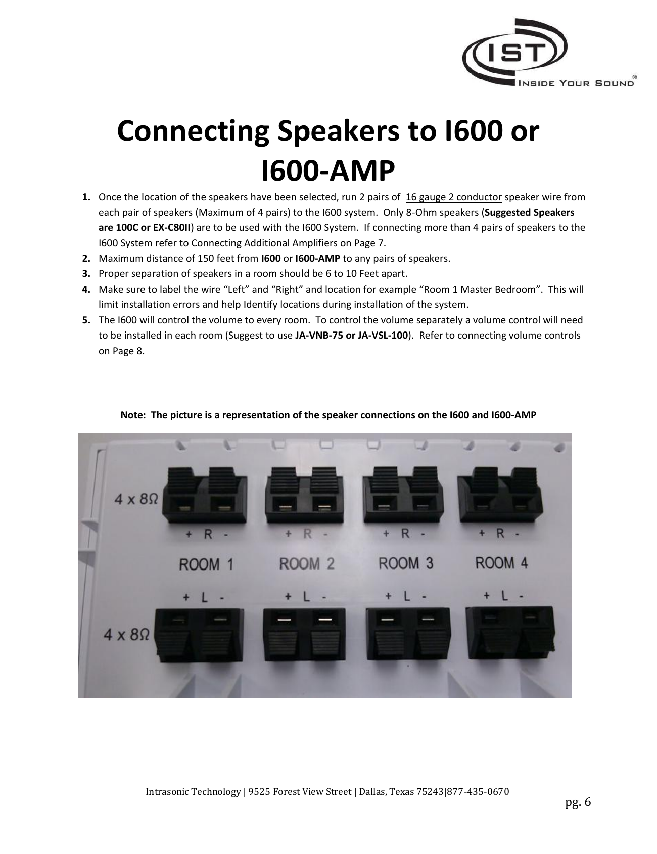
- Run 2 pairs of 16-gauge, 2-conductor speaker wire from each pair of speakers (maximum 4 pairs) to the I600. Only 8-ohm speakers (e.g. 100C or EX-C80II) should be used.
- Maximum distance from I600 or I600-AMP to any speaker pair is 150 feet.
- Space speakers 6–10 feet apart within a room.
- Label wires "Left" and "Right" with the room location (e.g. "Room 1 Master Bedroom") to avoid installation errors.
- Volume is controlled centrally by the I600 by default; to control volume per room, install a volume control (e.g. JA-VNB-75 or JA-VSL-100).
- If connecting more than 4 pairs of speakers, add an I600-AMP (see below).
Connecting Additional Amplifiers (I600-AMP, Optional)
An unlimited number of I600-AMP amplifiers can be added per system, each supporting up to 4 additional speaker pairs.
- Mount the I600-AMP in a closet or out-of-sight location, within 6 feet of a standard 110V outlet. Maximum distance from the I600 is 150 feet, using 22 AWG 75-ohm coaxial cable (RG59) with RCA connectors.
- Surface-mount the I600-AMP securely to the wall (screws not included).
- Run RCA audio cables from the I600's AMP OUT to the I600-AMP's AMP IN.
- To chain additional amplifiers, run RCA cables from one I600-AMP's AMP OUT to the next I600-AMP's AMP IN.
Connecting Volume Controls (Optional)
- Volume controls (e.g. JA-VNB-75 or JA-VSL-100) are only needed for independent per-room volume; without them, the I600 controls volume for the entire system.
- Run 2 pairs of 18-gauge, 2-conductor speaker wire from the I600 or I600-AMP to the volume control, then from the volume control to each speaker pair (max 4 pairs). Only 8-ohm speakers should be used.
- Match the L+ terminal on the I600/I600-AMP to the L+ terminal on the volume control's amplifier input, continuing for all matching terminals.
- Label each speaker pair "Left" and "Right" and connect to the correct Speaker Output terminal on the volume control (e.g., speaker one left+ wire to output L+, left- wire to output L-).
Connecting an Auxiliary Wall Plate (Optional)
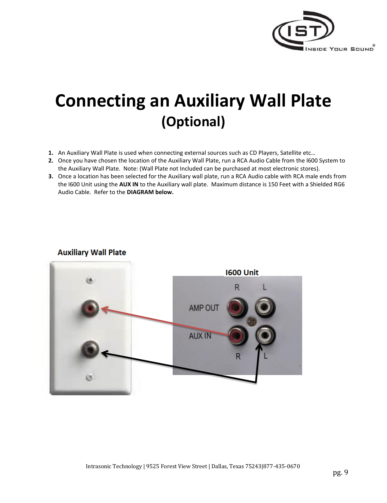
Used for external sources such as CD players or satellite receivers (wall plate not included — available at most electronics stores).
- Choose a location for the auxiliary wall plate.
- Run an RCA audio cable with male ends from the I600's AUX IN to the auxiliary wall plate.
- Maximum distance is 150 feet using shielded RG6 audio cable.
Installing the I600 Into the Wall
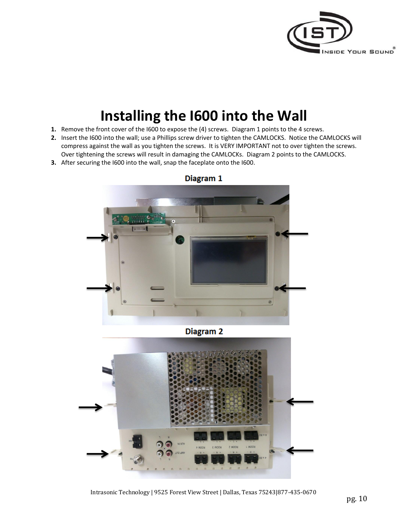
- Remove the front cover of the I600 to expose the 4 mounting screws.
- Insert the I600 into the wall and use a Phillips screwdriver to tighten the CAMLOCKS. The camlocks compress against the wall as the screws tighten — do not over-tighten, or you will damage the camlocks.
- After securing the I600 into the wall, snap the faceplate onto the unit.
Support
Intrasonic Technology | 9525 Forest View Street, Dallas, TX 75243 | 877-435-0670 | www.intrasonictechnology.com
Regulatory / FCC
This device complies with Part 15 of the FCC Rules and has been tested to Class B digital device limits. Operation is subject to: (1) this device may not cause harmful interference, and (2) it must accept any interference received. Changes or modifications not expressly approved by the party responsible for compliance could void the user's authority to operate the equipment. This equipment complies with FCC radiation exposure limits for an uncontrolled environment and should be installed/operated with a minimum distance of 20cm.