
Intrasonic V304KIT-R Color Video Door Phone / Intercom — Installer's Manual
Full installer's manual for the Intrasonic V304KIT-R Color Video Door Phone/Intercom system, covering wiring, jumper configuration, and mounting for up to 4 door stations and monitors.
Full text manual (for reference)
Installer's manual for the Intrasonic Technology Color Video Door Phone / Intercom Kit (Model V304KIT-R) — a wired video door phone and room monitor system with picture memory, supporting up to 4 door stations and 4 room monitors in a single daisy-chained system.
Safety & Installation Warnings
- To reduce risk of electrical shock, this system must be installed by a qualified installer or dealer.
- Do not expose any parts of the system to moisture — the apparatus should not be exposed to dripping, splashing, or objects filled with liquid.
- Do not locate inside monitors back-to-back or on walls facing each other — this can cause system feedback. Keep inside stations at least 10 feet apart.
- Keep all video door phone wiring away from other in-wall wiring, and at least 18 inches from any AC wiring, dimmer controls, or fluorescent light fixtures — proximity can cause humming or buzzing.
- Do not staple wires/cables or use wire splices.
- Use only approved products with the system; locate stations away from heat sources; label all cable runs.
- If using the separate remote power supply, use a dedicated power line to avoid humming/buzzing noise.
Power Supply Options
- Local plug-in supply (wall wart): Included with each monitor station; plugs into an available outlet at each monitor.
- Optional remote-mounted power supply: Can be mounted in a closet or other out-of-sight location. Powers up to 4 monitors and 4 door stations, with wires run inside the wall cavity so no wires are exposed at the monitor.
General Wiring Requirements
- A wiring harness (~35 ft.) is provided. For longer runs, use 4-conductor, 20 AWG (minimum) wire. Total system length from the first monitor to the last camera should not exceed 400 feet.
- Wiring from a remote power supply to the monitors must be 18 AWG (minimum), 2-conductor wire. Power is run to each monitor — cameras do not require power from the power supply.
- Cameras should be installed at approximately eye height (60–68 inches).
- Monitors are "daisy chained" together — the output of one monitor wires to the input of the next, up to a maximum of 4 monitors per system.
- If building your own cable instead of using the provided harness: connect leads to a 4-conductor cable for monitor/camera connections, matching pin 1 to pin 1 on both ends. Cover connections with wire nuts or shrink tubing. Power leads use a separate 2-conductor cable, with the power supply's positive (+) lead connected to the (+) terminal on the monitor's PCB.
Door Camera Connections
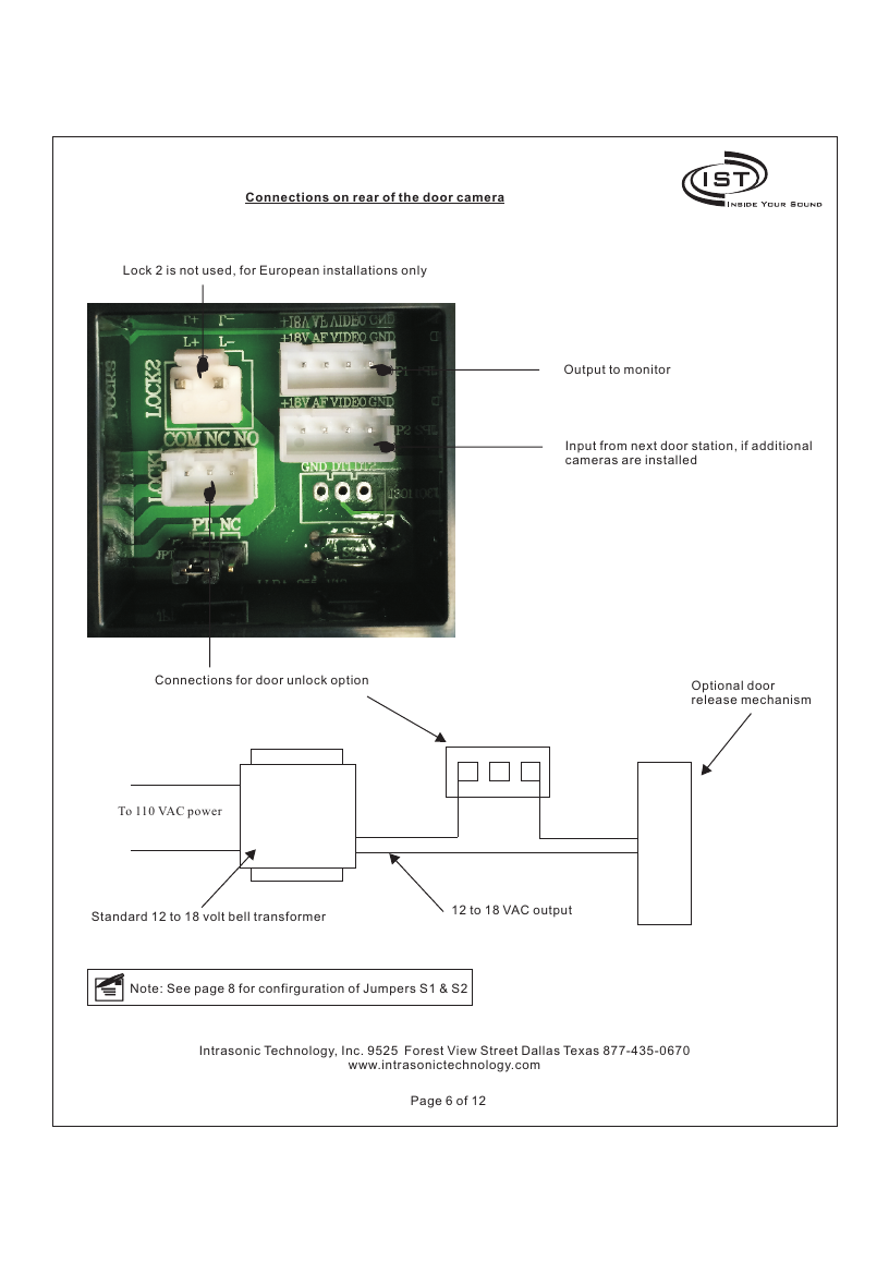
The door camera provides an output to the monitor, and an input from the next door station if additional cameras are daisy-chained. Lock 2 is unused (European installations only). For door unlock, an optional door release mechanism connects through the wiring shown, powered from 110VAC through a standard 12–18 volt bell transformer providing 12–18VAC output. See jumper configuration (S1 & S2) below for multi-camera setups.
System Wiring (Daisy Chain)
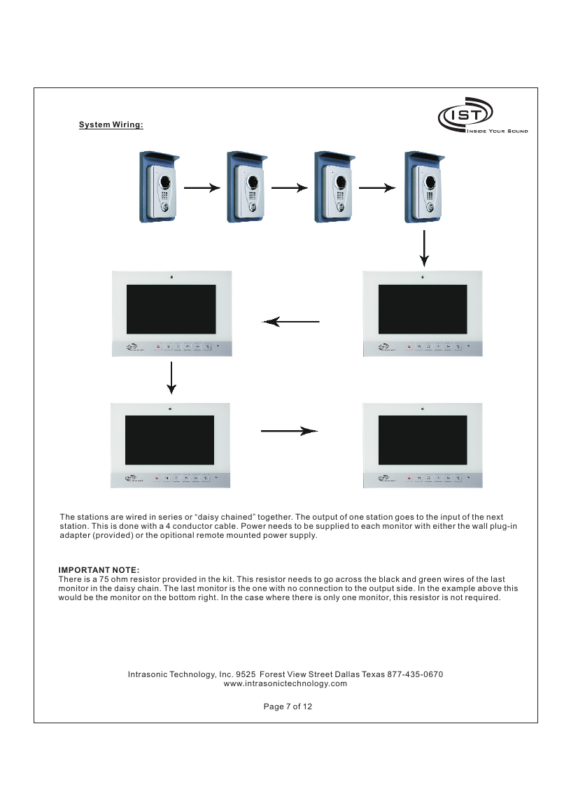
Important: A 75 ohm resistor (provided in the kit) must be placed across the black and green wires of the last monitor in the daisy chain (the monitor with no connection on its output side). If there is only one monitor in the system, this resistor is not required.
Preparing Components: Jumper Configuration
Door Station Jumpers (S1 / S2)
For multiple door stations, jumpers on the back of each door station must be cut according to how many stations are installed:
| Configuration | Jumper S1 | Jumper S2 |
|---|---|---|
| 1 door station | Do not cut | Do not cut |
| 2 stations — 1st station | Do not cut | Do not cut |
| 2 stations — 2nd station | Cut | Do not cut |
| 3 stations — 3rd station | Do not cut | Cut |
| 4 stations — 4th station | Cut | Cut |
Room Monitor Jumper (AF / NC)
- 1 monitor — leave jumper in AF position (factory default).
- 2 or more monitors — switch all but one monitor's jumper to NC position (leave exactly one in AF). E.g., for 3 monitors, 2 must be NC and 1 stays AF — it doesn't matter which two.
Installing the Door Station
- Select a mounting height with the camera at approximately eye level for a visitor. Using the rain shield as a template, mark the 4 mounting hole locations and the large square wire-access hole.
- Drill the square hole for wiring, then place anchoring devices suitable for the wall material in the 4 mounting holes.
- Mount the rain shield to the wall with the rain shield gasket between the wall and the shield. Place a rubber ring on each screw before installing, to help prevent water leakage behind the camera.
- Using the allen wrench provided, remove the top and bottom screws to remove the door station cover.
- Wire the provided 4-conductor cable connector to the in-wall cable, then plug into input jack JP1 on the back of the door station (a second door station's cable plugs into JP2).
- Insert the door station gasket, attach the door station to the rain shield using the 4 screws and rubber seal rings provided.
- Caution: There is a soft rubber protector on the call button — take care not to lose this cover when removing the door station front cover.
- Reattach the door station face plate and reinstall the top/bottom screws with the allen wrench.
Installing the Room Monitor
- Cut a rectangular hole in the wall for the mounting bracket, approximately 2" x 2.3".
- Using anchors/screws suitable for sheetrock (or other wall material), mount the monitor holding bracket — tighten all 4 corners flush against the wall.
- Bring wires out of the hole and plug into the appropriate jack on the rear of the monitor: input cables from a camera or another monitor go into the center connector (IN); a second cable to another monitor goes into the connector on the right (OUT).
- For a wall plug-in power supply, plug into the 2-pin connector on the left using the adapter provided. For a remote-mounted power supply, wire its 2 leads to the provided 2-pin adapter (red & black) and plug into the same connector.
Additional Safety Instructions
- Read and keep these instructions; heed all warnings and follow all instructions.
- Do not use this apparatus near water; clean only with a dry cloth; do not block ventilation openings.
- Only use attachments/accessories specified by the manufacturer; do not expose to moisture (shock/fire hazard, voids warranty).
- Do not service this product yourself — contact a qualified local dealer for service.
- Substituting non-Intrasonic Technology products may result in electrical shock or other hazards.
WARNING: To reduce the risk of fire or electric shock, do not expose this apparatus to rain or moisture. CAUTION: Do not remove the cover/back — no user-serviceable parts inside; refer to qualified service personnel.
FCC Compliance
This device complies with Part 15 of the FCC rules: (1) it may not cause harmful interference, and (2) it must accept any interference received, including interference that may cause undesirable operation. Tested and found to comply with Class B digital device limits under Part 15. Changes or modifications not expressly approved by the party responsible for compliance could void the user's authority to operate the equipment.
Intrasonic Technology, Inc. — 9525 Forest View Street, Dallas, TX. Support: 877-435-0670, www.intrasonictechnology.com