
Intrasonic RETRO MyDoor™ — Installation Instructions
Installation instructions for the Intrasonic Technology RETRO MyDoor video door station retrofit unit, covering wiring, connectors, and mounting.
Full text manual (for reference)
Installation instructions for the Intrasonic Technology RETRO MyDoor™ — a video door station retrofit unit designed to install onto an existing RETRO intercom master station. This page summarizes the key mounting and wiring steps, connector layout, and reference diagrams; the full downloadable PDF has the complete step-by-step photos.
Before You Begin
- Ensure the door unit has been powered on and connected to the home Wi-Fi before installation — refer to the Operation Manual for initial Wi-Fi setup.
- Insert the Micro SD card prior to installation of the door unit.
- Position the door unit where it will be installed first, so you know the angle the camera needs to be adjusted to. The camera sits in a ball-joint housing and can be pivoted to the desired viewing direction.
Installation Steps
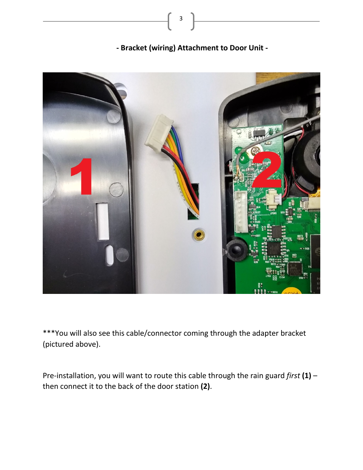
- Route the two (2-conductor) cables coming out of the back of the adapter bracket through the bracket opening before installation.
- Route the door station connector cable through the rain guard first, then connect it to the back of the door station.
- Connect the adapter bracket back to the RETRO master station via three wires, the same way every other station connects. The adapter bracket's terminal labels differ from the master station's, but the values match:
- V+ (Adapter Bracket) → +15V (RETRO Master, Door 1/2 terminal)
- G (Adapter Bracket) → 0V (RETRO Master, Door 1/2 terminal)
- L (Adapter Bracket) → LINK (RETRO Master, Door 1/2 terminal)
- With the other wiring routed through the bracket opening and the RETRO system wiring connected to the back of the bracket, position it appropriately and adhere it to the wall/housing.
- Route the two-conductor cables from the back of the bracket through the opening of the rain guard and connect them to the back of the door unit.
- Position the rain guard on the wall. Apply caulk to the top and sides of the guard AND the adapter bracket (bottom left open) for weather protection. The station is weather-resistant, NOT weather-proof.
- Screw the MyDoor™ unit to the adapter bracket, securing the rain guard in place behind it.
- Position the faceplate over the MyDoor™ and secure it with the included bolts.
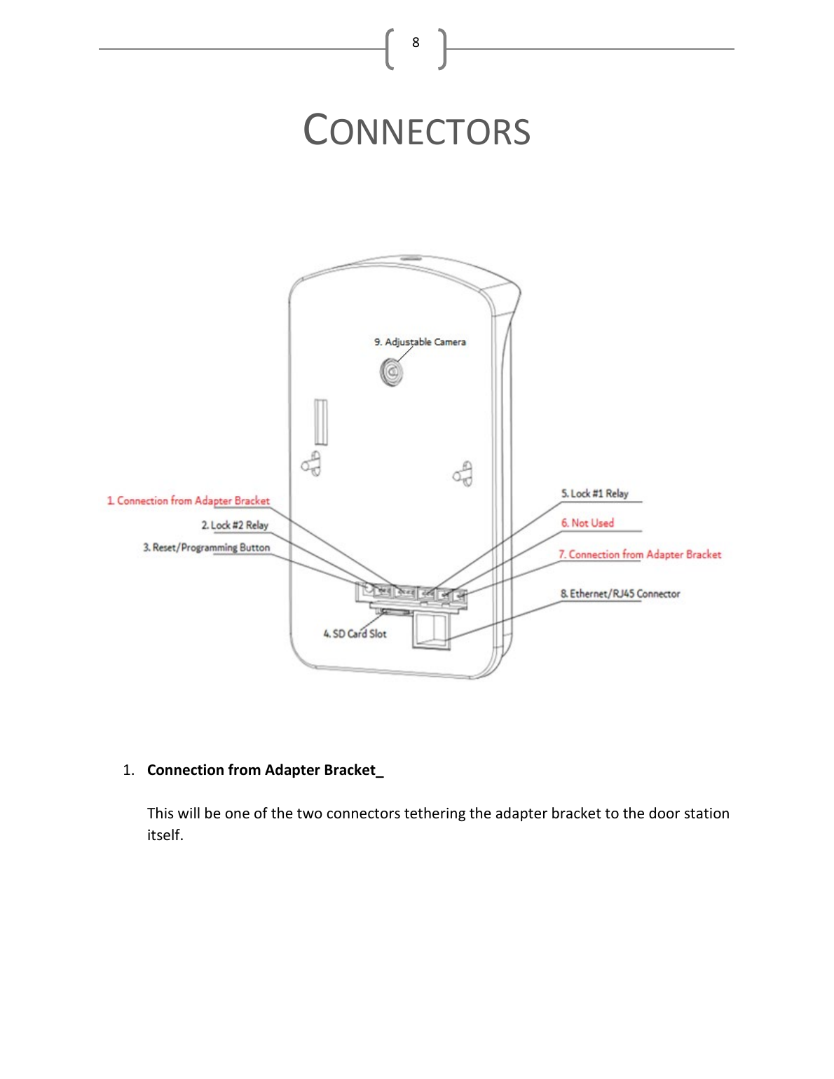
Rear Connector Panel
Reference for the connectors on the back of the door unit:
- Connection from Adapter Bracket (one of two connectors tethering the adapter bracket to the door station)
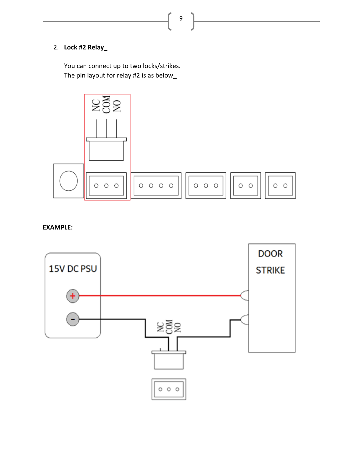
- Lock #2 Relay — you can connect up to two locks/strikes
- Reset/Programming button — serves as both the reset and initial programming button; refer to the Operation Manual for the programming procedure. Holding this button for 15 seconds resets the unit.
- SD Card Slot — internal storage expandable up to 32GB using a standard Micro SD card. The oldest data is overwritten once the card reaches maximum capacity.
- Lock #1 Relay — you can connect up to two locks/strikes
- Not Used — this connector is not used on the RETRO version of the MyDoor™
- Connection from Adapter Bracket (second of the two connectors)
- Ethernet/RJ45 Connector — connect a CAT5 cable to this port (from your home router or switch) for the best data transfer (optional)
- Adjustable Camera — the camera angle can be adjusted prior to installation
Manufacturer
Intrasonic Technology, Inc. — 9525 Forest View Street, Dallas, Texas — 877-435-0670 — www.intrasonictechnology.com