
Ecolink ECDWZWAVE25ECO Z-Wave Plus Door/Window Sensor (Gen5) — Installation Instructions
Installation instructions for the Ecolink ECDWZWAVE25ECO Z-Wave Plus Door/Window Sensor (Gen5) — a battery-powered magnetic contact sensor reporting open/closed and tamper status to your Z-Wave network.
Full text manual (for reference)
Installation instructions for the Ecolink ECDWZWAVE25ECO Z-Wave Plus Door/Window Sensor (model DW-ZWAVE2) — a battery-powered magnetic contact sensor that reports open/closed status and tamper condition to a Z-Wave network.
Overview
- Z-Wave enabled device providing open/closed position status
- Transmits open/closed status to the Z-Wave network
- Reports a tamper condition if the sensor cover is opened
Specifications
| Spec | Value |
|---|---|
| Use | Indoor use only |
| Operating frequency | 908.42 MHz |
| Operation range | Up to 100 ft. (30.5 m) line-of-sight |
| Operating temperature | 32°–120°F (0°–49°C) |
| Battery type | 3V Lithium CR123A |
| Battery life | Approximately 3 years |
| FCC ID / IC | XQC-DWZ1 / 9863B-DWZ1 |
Package Contents
- 1 Door/Window Sensor
- 1 Sensor Mounting Bracket
- 2 Screws for Sensor Mounting Bracket
- 1 Adhesive tape for Sensor Mounting Bracket
- 1 Sensor Magnet
- 2 Screws for Sensor Magnet
- 1 Adhesive tape for Sensor Magnet
An optional brown plastic housing set is also included as an alternative to the standard white housing, for use on darker doors/windows.
Network Inclusion
Both the Z-Wave controller and the sensor must be placed into inclusion mode at the same time to add the sensor to the network.
- Place the Z-Wave controller into inclusion mode.
- Remove the plastic pull-tab from the back of the sensor to connect the battery and activate inclusion. The LED will go solid red, then turn off when inclusion completes.
- Test by placing the magnet near the sensor — one LED flash means success. Slow flashing for 5 seconds means inclusion failed; repeat the process.
To repeat inclusion manually: remove the cover, remove the battery for 5 seconds, reinsert the battery, and replace the cover.
Key Points to Remember
- Controller inclusion mode must be activated before sensor inclusion mode.
- The sensor can only belong to one controller network at a time.
- Removing the pull-tab connects the battery and initiates inclusion; alternatively, remove the battery for 5 seconds to trigger the same behavior.
- The plastic pull-tab must be removed to enable sensor operation.
- The sensor automatically enters inclusion mode at power-up.
- Exclusion (removing the sensor from a network) follows the same procedure as inclusion.
Installation
Step 1 — Identify Location for Sensor and Magnet
The sensor body has a line and directional arrow indicating where the magnet should be placed relative to it. Mount the sensor on the fixed frame/jamb (not the moving door or window) and the magnet on the moving part. Verify orientation before mounting — see mounting diagrams below.
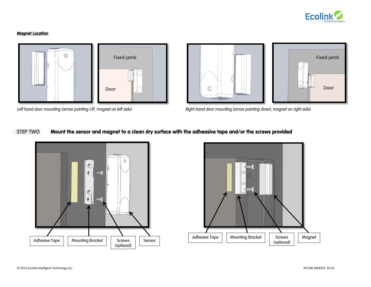
Step 2 — Mount the Sensor and Magnet
Mount the sensor and magnet to a clean, dry surface using the adhesive tape and/or the screws provided.
- Attach the mounting bracket to the frame first.
- The sensor can slide onto the bracket in two orientations — the tab should engage the back of the sensor for a secure fit.
- Confirm the bracket orientation before attaching, since it determines the required sensor orientation.
- Slide the sensor onto the bracket until the tab engages. Note: adhesive tape may damage some surfaces if removed later.
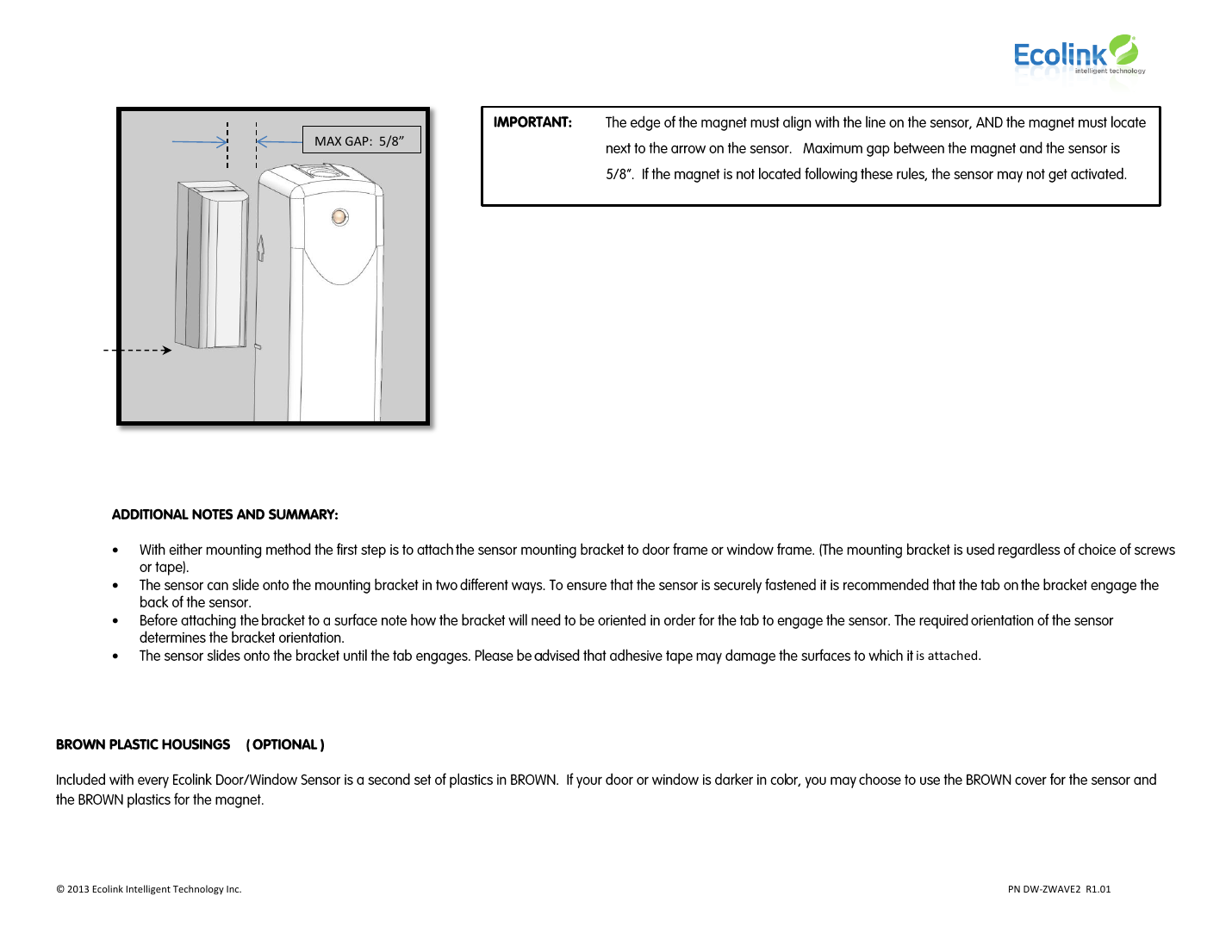
Important: The edge of the magnet must align with the line on the sensor, and the magnet must be located next to the arrow on the sensor. The maximum gap between the magnet and sensor is 5/8". If the magnet is not positioned according to these rules, the sensor may not activate correctly.
Compliance
This device complies with FCC Class B digital device rules and Industry Canada RSS license-exempt standards. If interference occurs, try reorienting/relocating the receiving antenna, increasing separation between the sensor and other equipment, or connecting the affected equipment to a different circuit. Unauthorized modifications may void the user's authority to operate this equipment.
Warranty
3-year warranty from date of purchase covering defects in material and workmanship. Excludes damage from shipping, misuse, or unauthorized modification. Remedy at Ecolink's option is repair or replacement.