
DoorBell Fon DP28C Intercom System — User & Installation Manual
User and installation manual for the DoorBell Fon DP28C phone-line door intercom system, including wiring diagrams and troubleshooting.
Full text manual (for reference)
User and installation manual for the DoorBell Fon™ intercom system (DP28C Controller) — a phone-line-based door intercom that lets you answer your door or gate from any telephone in the house.
Overview
The DoorBell Fon works with your incoming regular telephone line (or as a stand-alone unit) and can integrate with multi-line, PBX, or Key phone systems. Optional modules add door-lock release, doorbell chime activation, or full intercom functionality.
Kit Contents
- 1x DP28C Controller
- 1x User Guide (with warranty registration card)
- 1x Door Station (optional)
Installation — Main Controller
- Locate where your incoming phone line (POTS) enters the house — this is where you'll connect the Main Controller. It should be the first device on the line, after any security system but before the phones. For DSL or VoIP, refer to the wiring diagrams below.
- Cut the incoming line and connect one end to the controller's From TEL. Company position, and the other cut end to To Phones (jack connectors or screw terminals both work).
- Alternatively, disconnect the POTS line at your distribution panel and wire fresh phone wire from To Phones back to the distribution panel.
- Mount the controller between the phone line entry point and the distribution panel, before all phones in the home.
Installation — Door Station
- Choose a mounting location. For DP28-NIT/DP28-NWT models, remove the bottom screw to detach the Door Station from its mounting bracket, then mount the bracket.
- Connect a pair of wires to the two screws at the upper-left corner on the back of the Door Station, and run them to the Main Controller.
- Connect the wires to either the Door 1 or Door 2 screw terminals on the controller (observe polarity) — each provides a different ring pattern; test both to choose your preference.
- Mount the Door Station back onto its bracket.
Installer Notes
- Not compatible with Motorola telephone systems.
- Up to 4 Door Box Controllers can be connected in series for a total of 8 zones.
- Incorrect Door Station polarity: unit will ring but no communication, and the LED won't glow.
- With the Intercom Module add-on, only 1 Door Station can be used, on the "Door 1" terminal only.
- Shorting the "Door 1" or "Door 2" pair rings the phones without damage — this allows using an existing doorbell button in series with a 300-ohm resistor.
- Connecting "To Phones" to a phone system loses the distinctive door ring (a Tone Generator can restore it over paging).
- Optional chips: N8H (more rings), N1H (fewer rings), N8NC (connects only to "To Phones" of a PBX/KSU without a CO line).
- Two fuses on the board: F2 (phone line) and F1 (AC power line).
- Check total REN (Ringer Equivalency Number) on all connected phones — above 4.6 requires a Ring Booster.
- Install Lightning Surge Protection on the AC circuit and incoming phone line — lightning damage is not covered by warranty.
Powering Up
Plug the controller cord into a 110V outlet. The Door Station's LED should glow dimly if polarity is correct; if not, double-check the (+) and (−) connections.
Wiring Diagram — Using Existing Doorbell Wires
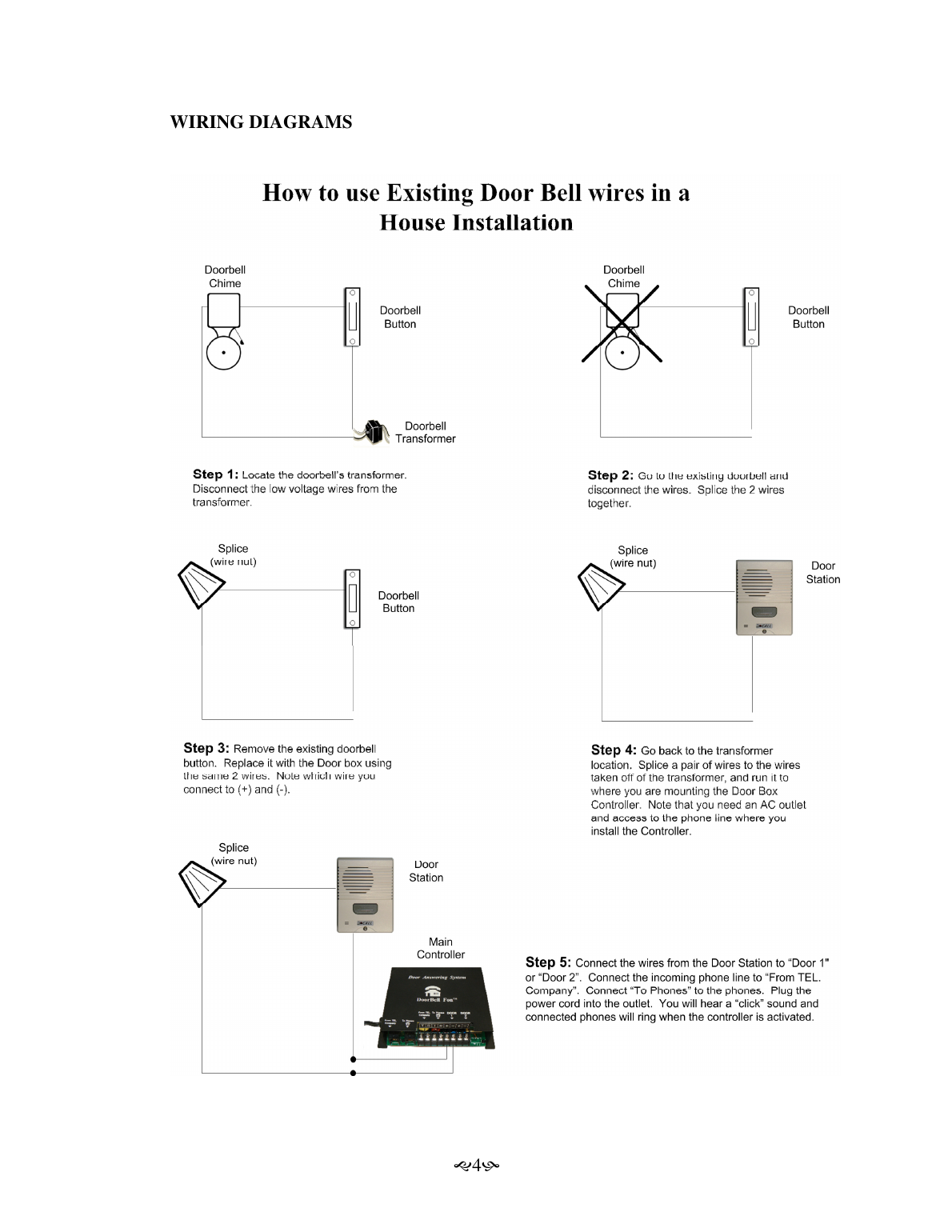
- Locate the doorbell's transformer and disconnect its low-voltage wires.
- Disconnect the wires at the existing doorbell and splice them together.
- Remove the existing doorbell button and replace it with the Door Station, using the same 2 wires (note polarity).
- At the transformer location, splice a new pair of wires and run them to the Main Controller mounting location (needs an AC outlet and phone line access).
- Connect the Door Station wires to "Door 1" or "Door 2," the incoming phone line to "From TEL. Company," and "To Phones" to the house phones. Plug in the power cord — you'll hear a click and connected phones will ring when activated.
Operating Instructions and Q&A
- Answering the door: Simply pick up the phone — you'll be automatically connected to the Door Station.
- Missed ring window: After the ring series stops, you have ~25 seconds to pick up and press the flash key (or hook switch) to connect.
- Call waiting: If you're on a call when the Door Station is pressed, you'll hear a signal — press flash/hook switch to talk to the door, then again to return to your call.
- Answering machines: Set to 2 rings if you want it to answer the door, or over 3 rings if not.
- Distinguishing rings: Normal ring = 1 sec on / 2 sec off. Door 1 = 1 sec on / 1 sec off. Door 2 = 1 sec on / 0.5 sec off / 1 sec on / 1 sec off.
- Volume adjustment: A potentiometer on the Door Station PC board (brass/aluminum stations) adjusts volume — turn clockwise to increase.
- Door/gate release: The DP29-SW/IM add-on controller opens an electric door or gate by pressing (*) on the phone keypad.
- REN calculation: Max operating range 4.6–5.0. Sum the REN labels on all connected phones, caller ID units, and answering machines; if exceeded, add a Ring Booster.
Troubleshooting
| Symptom | Solution |
|---|---|
| Phone rings but can't talk on it | Check LED brightens when Door Station pressed; verify (+)/(−) polarity on the Main Controller; door station mic/speaker may be faulty. |
| Can talk to Door Station but no dial tone | Check/replace fuses (F1 = 0.5A/250V, F2 = 0.25A/250V). A non-standard phone set may need replacement. |
| Caller ID doesn't work with door rings | Expected behavior for door rings. If total REN > 4.6, add a Ring Booster or replace F2 with a 0.25A/0.5A fast-blow fuse. |
| Static when Door Station is pressed | Unplug and reverse the AC plug 180°. For DSL, split data/phone signal before the Main Controller. Ensure an alarm system is installed in series before the Main Controller. |
| Phone won't ring | Swap Tip/Ring at "To Phones" terminal; check REN total; verify wiring between Door Station and Main Controller. |
| Squealing/feedback noise | Remove plastic film from metal faceplates; adjust the R11 potentiometer counter-clockwise; add foam/insulation in the mounting box; avoid corner installs. |
| Incoming calls trigger Door Station instead | Reverse tip/ring wires (usually green/red) at the wall outlet; replace non-standard phone sets. |
Return for Repair
Call ACNC Customer Service for an RMA number before returning a unit. Pack in the original carton (or sturdy corrugated cardboard, non-static material — no plastic wrap, Styrofoam peanuts, or foam beads). Include your name, address, phone number, RMA number, and problem description. Ship prepaid via UPS or USPS.
Mail to: ACNC/Doorbell Fon™, Attn: Warranty/Repair Dept, RMA# (on mailing label), 1989 University Ln., Unit H, Lisle, IL 60532, U.S.A.
Warranty
ACNC warrants hardware products against defects in material/workmanship for one year from purchase (non-transferable); two years for registered products (labor and materials). Excludes damage from power surges/lightning or improper installation.
Technical Support
Tel: 1.630.241.2800 · www.homephone.com · info@homephone.com