
Channel Vision C-0441 — 110 Telecom Module Installation Instructions
Installation instructions for the Channel Vision C-0441 — a high-capacity 100-pair phone distribution panel with a built-in security panel loop.
Full text manual (for reference)
Installation instructions for the Channel Vision C-0441 — a versatile, high-capacity phone distribution panel that mounts a standard 100-pair 110-type cross-connect block on a structured wiring module. Supports up to 24 telephone drops of 4 lines each, and includes a switch-based security panel loop (more reliable than the typical RJ-31X jack).
Wiring the C-0441 for Typical Telephone Use (24 drops, 4 lines each)
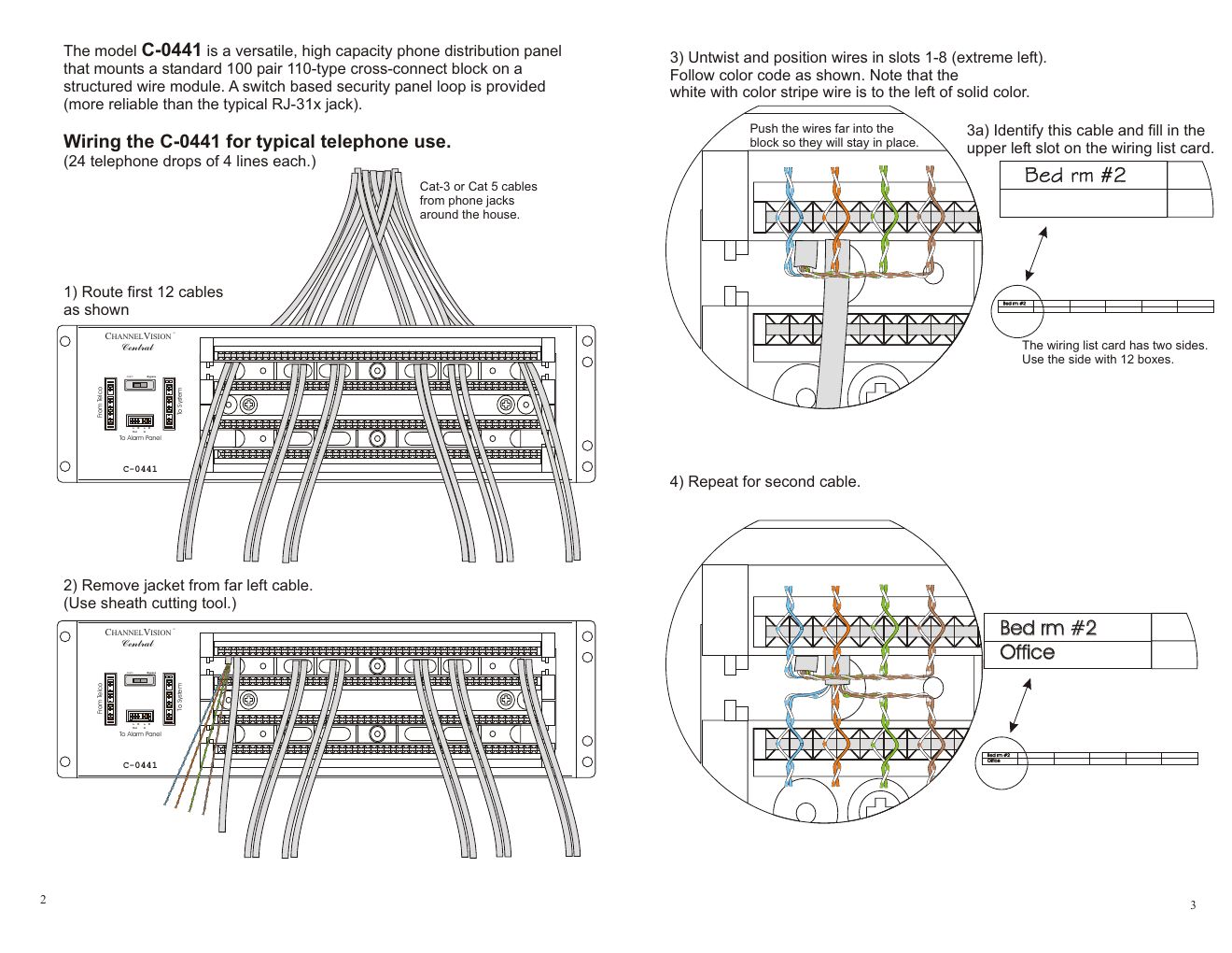
- Route the first 12 Cat-3 or Cat-5 cables (from phone jacks around the house) into the panel as shown.
- Remove the jacket from the far-left cable using a sheath cutting tool.
- Untwist and position the wires in slots 1–8 (extreme left), following the color code — note that the white-with-color-stripe wire goes to the left of the solid color wire. Push wires far into the block so they stay in place. Identify the cable and fill in the upper-left slot on the wiring list card (the card has two sides — use the side with 12 boxes).
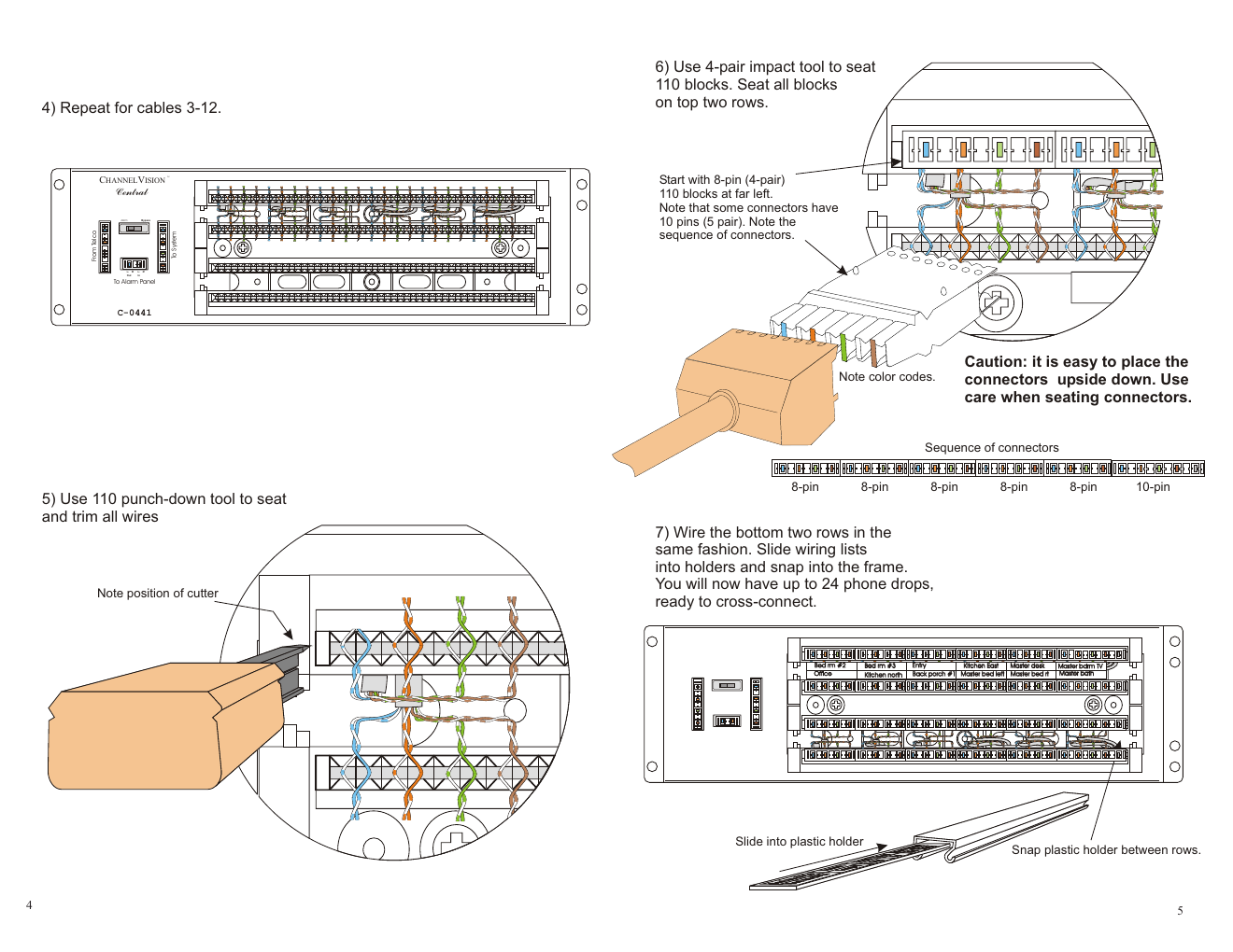
- Repeat for the second cable, and then for cables 3–12.
- Use the 110 punch-down tool to seat and trim all wires (note the position of the cutter blade).
- Use a 4-pair impact tool to seat the 110 blocks, starting with 8-pin (4-pair) blocks at the far left — seat all blocks on the top two rows first. Note that some connectors have 10 pins (5-pair); watch the connector sequence, and be careful not to place connectors upside down.
- Wire the bottom two rows the same way. Slide wiring lists into their holders and snap the plastic holder between rows.
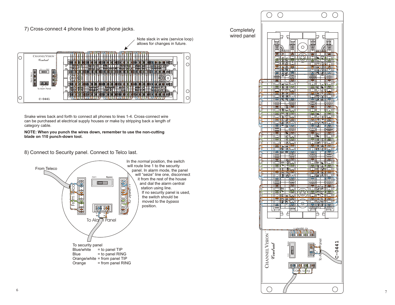
- Cross-connect 4 phone lines to all phone jacks — snake wires back and forth to connect all phones to lines 1–4. Cross-connect wire can be purchased at electrical supply houses, or made by stripping back a length of category cable. Leave slack in the wire (service loop) to allow for future changes. Note: use the non-cutting blade on the 110 punch-down tool when punching down these wires.
- Connect to the security panel, then connect to Telco last.
Installation Reference Photos
Security Panel Loop
In the normal position, the switch routes line 1 to the security panel. In alarm mode, the panel "seizes" line 1, disconnects it from the rest of the house, and dials the alarm central station using that line. If no security panel is used, move the switch to the Bypass position. Wiring to the security panel: Blue/white = to panel TIP, Blue = to panel RING, Orange/white = from panel TIP, Orange = from panel RING.
Warranty
Channel Vision Technology will repair or replace defects in material or workmanship free of charge in the USA for two years from the date of original purchase — no mail-in warranty card needed. Excludes shipping damage, failures from other products, and accident/misuse/abuse/alteration. Mail-in service: call (800) 840-0288 for a Return Authorization number before shipping. Channel Vision Technology, 234 Fischer Avenue, Costa Mesa, CA 92626 · (714) 424-6500 · (800) 840-0288 · www.channelvision.com