
ABB-Welcome M2302 Gateway — Installation Manual
Installation and configuration guide for the ABB-Welcome M2302 Gateway — building, floor, and apartment gateway modes plus line amplifier setup.
Full text manual (for reference)
Quick reference for the ABB-Welcome M2302 Gateway — a DIN-rail module used to segment an ABB-Welcome door communication system into independent sub-systems (building, floor, or apartment gateways) or to boost signal as a line amplifier. This page summarizes the safety essentials, operating modes, and DIP-switch configuration; the full downloadable PDF includes complete per-mode wiring diagrams.
Safety Warnings
- Electric voltage risk (100-240V): Work on the mains supply may only be performed by authorized electricians. Disconnect mains power before installation or disassembly.
- Install the device only if you have the necessary electrical engineering knowledge and experience — incorrect installation endangers life and can cause serious property damage (e.g. fire).
- Apply the "five safety rules" (DIN VDE 0105, EN 50110): disconnect from power, secure against reconnection, verify absence of voltage, connect to earth, and cover/barricade adjacent live parts.
- Use suitable personal protective equipment and only appropriate tools/measuring devices.
- The M2302 must be installed on DIN rails per DIN EN 50022 only.
Intended Use
The M2302 gateway is an integral part of the ABB-Welcome door communication system and operates exclusively with components from that system.
Operating Modes
A 3-position DIP switch block on the device sets its operating mode:
| Mode | DIP Switch (1/2/3) | Function |
|---|---|---|
| Building gateway | OFF / OFF / OFF | Enables one building as an independent sub-system (outdoor stations/guard units can be connected). Up to 60 such systems supported. Gateway address equals the riser number. |
| Floor gateway | OFF / OFF / ON | Enables a multi-apartment floor as an independent sub-system (another outdoor station can be added, e.g. at the floor entrance). Gateway address equals the minimum address of the indoor station in the sub-system. |
| Apartment gateway | OFF / ON / OFF | Enables one apartment as an independent sub-system (a 2nd confirmed outdoor station can be connected). Up to 99 such systems supported. Gateway address equals the apartment number. |
| Additional power supply mode | OFF / ON / ON | Provides an additional power source for systems with a system controller — useful when one system controller can't power all connected indoor stations in a building. |
| Line amplifier | ON / OFF / OFF | Strengthens the video signal and extends transmission distance on the bus line. |
Reference Diagrams
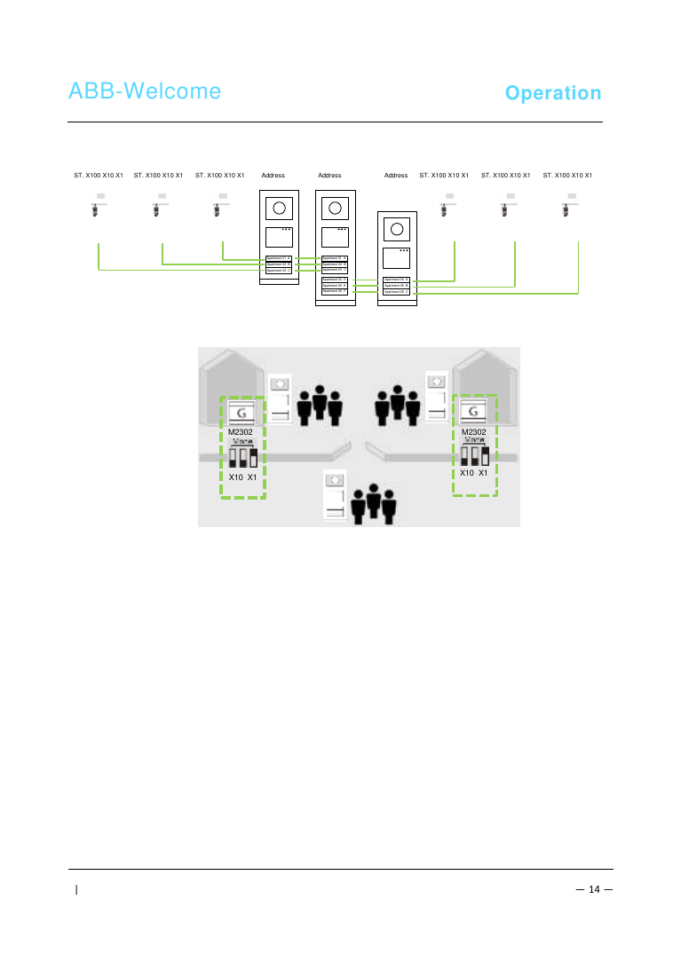
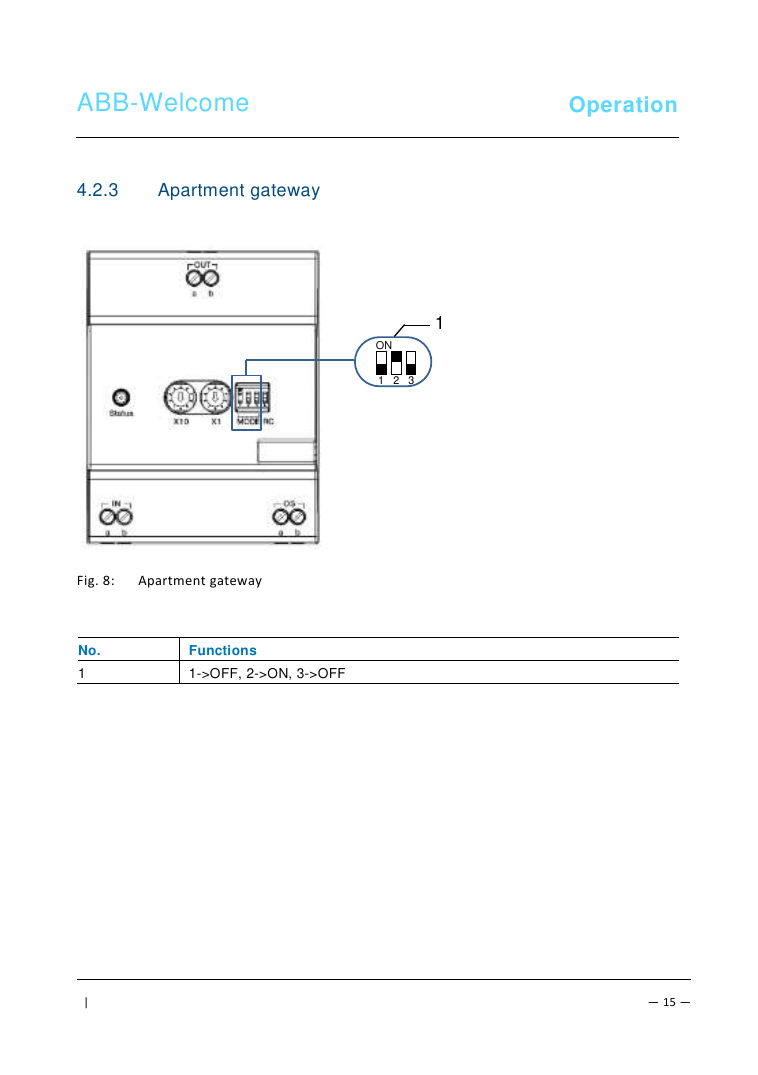
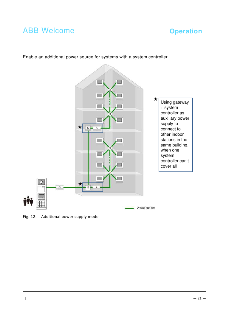
General Installation Instructions
- Terminate all wiring branches via a connected bus device (indoor station, outdoor station, or system device).
- Do not install the system controller directly next to the bell transformer or other power supplies (avoids interference).
- Do not run system bus wires together with 100-240V wires.
- Do not share cables between door opener wiring and system bus wiring.
- Avoid bridging between different cable types.
- Use only two wires for the system bus, even within a four-core or multi-core cable.
- Never route incoming and outgoing bus wiring inside the same cable when looping.
- Never install the internal and external bus inside the same cable.
Technical Data
| Operating temperature | -25°C to +55°C |
| Protection rating | IP 20 |
| Single-wire clamps | 2 x 0.28mm² – 2 x 1mm² |
| Fine-wire clamps | 2 x 0.28mm² – 2 x 1mm² |
| Bus voltage | 20-30V |