
Yale Real Living™ T1L Touchscreen Deadbolt with Z-Wave (YRD120-ZW) — Installation & Programming
Installation and programming quick reference for the Yale Real Living™ Key Free Touchscreen Deadbolt (Model T1L) with Z-Wave®.
Full text manual (for reference)
Installation and programming quick reference for the Yale Real Living™ Key Free Touchscreen Deadbolt (Model T1L) with Z-Wave®. This manual is a fully illustrated, diagram-only guide; the images below and the downloadable PDF walk through every installation step. This page summarizes the parts, install sequence, programming codes, and troubleshooting for quick lookup.
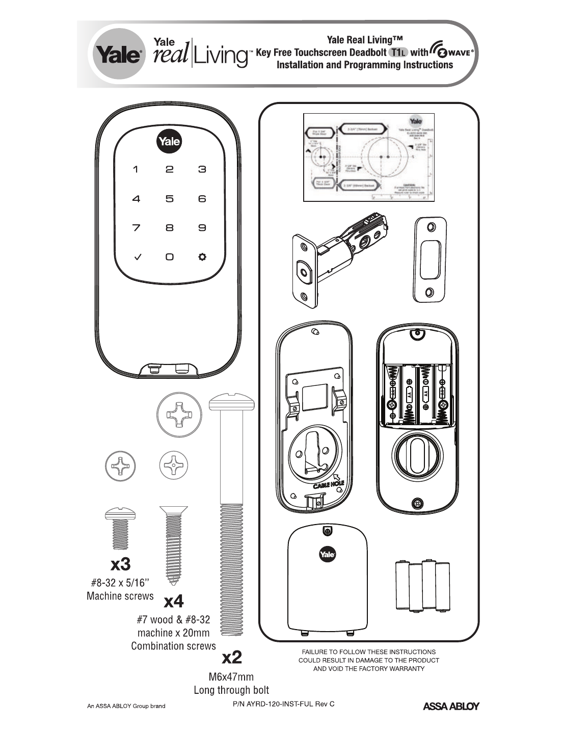
Parts & Hardware Included
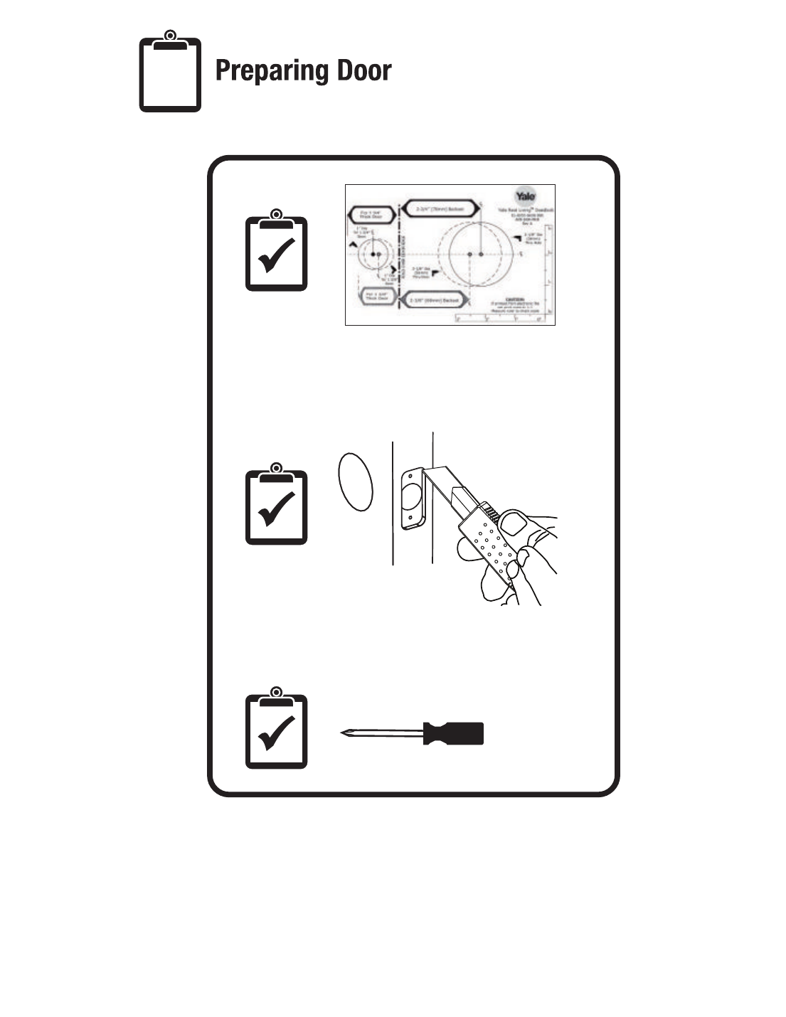
- Door-prep template with backset options: 2-3/4" (70mm) or 2-3/8" (60mm), 2-1/8" dia. thru hole, 1" dia. cross hole
- Latch bolt mechanism, strike plate, interior mounting plate (with cable hole), exterior touchscreen escutcheon, interior escutcheon with turnpiece and battery compartment (4 AA batteries)
- Screws: x3 #8-32 x 5/16" machine screws, x4 #7 wood & #8-32 machine x 20mm combination screws, x2 M6 x 47mm long through-bolts
- Tools needed: Phillips-head screwdriver, hole saw for door boring
Installation Steps
- Prepare the door — use the template to mark and bore the main cylindrical hole and cross bore per the backset selected.
- Install latch & strike plate — set latch to 2-3/8" (default) or 2-3/4" (optional, press and pull to adjust). Bolt must be in the retracted (unlocked) position before installing. Secure with 4 screws.
- Install touchscreen escutcheon — feed the connector cable through the door, align the exterior keypad unit outside and route the cable to the interior side.
- Install interior mounting plate — attach with 2 long screws, routing the cable through the labeled cable hole.
- Attach the cable assembly — connect the cable connectors in the correct orientation (see connector diagram — arrows must align), secure with the cable hook.
- Install interior escutcheon — secure with 3 screws; battery compartment holds 4 AA batteries.
- Install cover — attach the final cover plate over the assembled interior unit.
- Test operation — rotate the interior turnpiece and visually confirm the latch bolt extends/retracts correctly in the strike plate. Batteries must NOT be installed until the bolt is in the retracted (unlocked) position.
- Hand the lock — install batteries, then on the keypad: Press ⚙, Press 1, Press ⚙, enter new Master PIN code (4-8 digits), press ⚙ to complete. After entering the Master PIN, press any key to complete handing.
Programming — Creating the Master PIN Code
The Master PIN code must be created before any further programming. Max user codes = 100.
- Press ⚙ (gear key)
- Enter 4-8 digit Master PIN code
- Press ⚙
Creating User PIN Codes
- Enter Master PIN code, press ⚙
- Press 2, press ⚙
- Press 1, press ⚙
- Enter user number to create (1-100), press ⚙
- Enter 4-8 digit PIN code, press ⚙
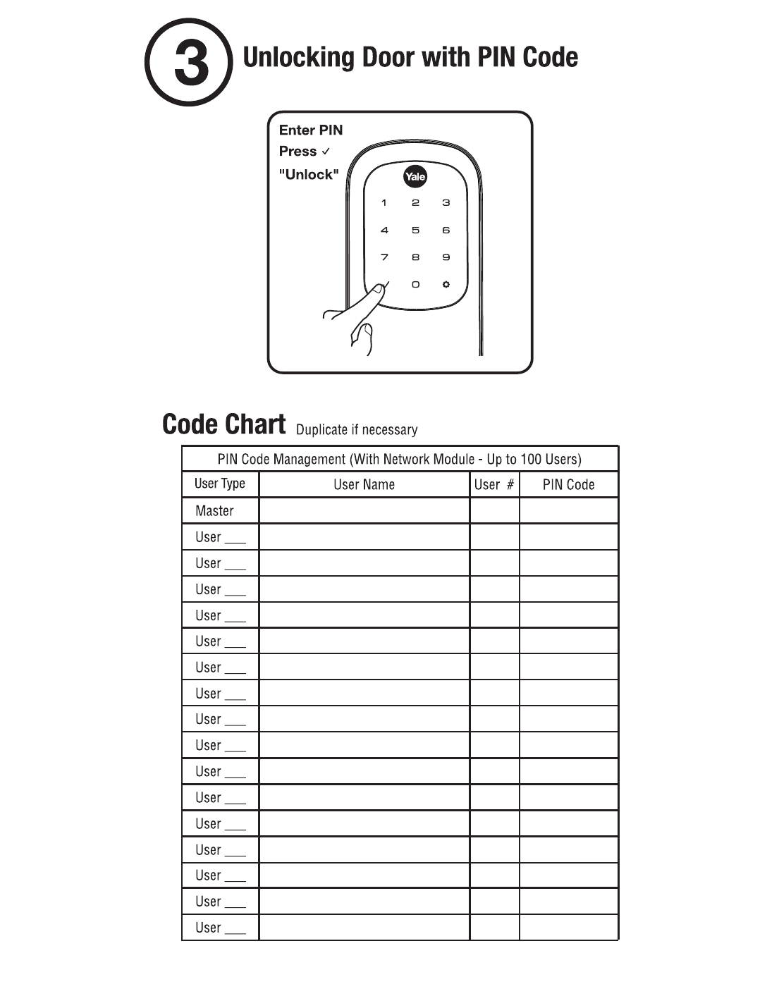
Unlocking the Door
Enter PIN, press ✓ ("Unlock").
Resetting to Factory Default
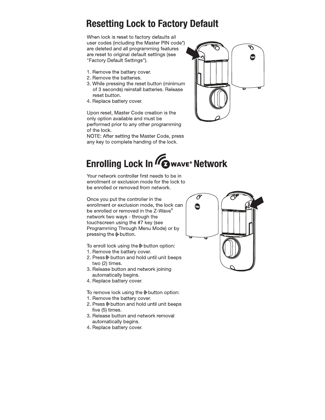
Resetting erases all user codes (including the Master PIN code) and restores all programming to factory defaults.
- Remove the battery cover and batteries.
- While pressing the reset button (minimum 3 seconds), reinstall the batteries, then release the reset button.
- Replace the battery cover.
After a reset, creating the Master Code is the only option available and must be done before any other programming. After setting the Master Code, press any key to complete handing of the lock.
Enrolling in a Z-Wave® Network
Put your network controller into enrollment or exclusion mode first. Enroll/remove either through the touchscreen (Menu 7, see Programming Menu below) or via the wireless button on the interior unit.
- To enroll (wireless button): remove battery cover, press and hold the wireless button until the unit beeps twice, release — network joining begins automatically, replace battery cover.
- To remove (wireless button): remove battery cover, press and hold the wireless button until the unit beeps five times, release — network removal begins automatically, replace battery cover.
Programming Menu (Master PIN Code Required)
Enter the 4-8 digit Master PIN code followed by ⚙, then enter the menu digit for the desired function followed by ⚙. Default settings shown in bold.
- 1 — Master PIN Code Setting
- 2 — User PIN Code Registration: 1 Register, 3 Delete
- 3 — Advanced Lock Settings: 1 Automatic Re-lock (1 Enable / 3 Disable), 3 One Touch Locking (1 Enable / 3 Disable), 5 Handing the Lock (performs automatic handing)
- 4 — Audio Mode: 1 Enable / 3 Disable (choose Disable for quiet areas)
- 6 — All Code Lockout Mode: 1 Enable / 3 Disable
- 7 — Network Setting: 1 Join the network / 3 Exit the network
Factory Default Settings
| Setting | Factory Default |
|---|---|
| Master PIN Code | Registration required |
| Automatic Re-lock | Disabled |
| One Touch Locking | Enabled |
| Audio | Enabled |
| Automatic Re-lock Time | 30 seconds |
| Wrong Code Entry Limit | 5 times |
| Shutdown Time | 60 seconds |
Key Definitions
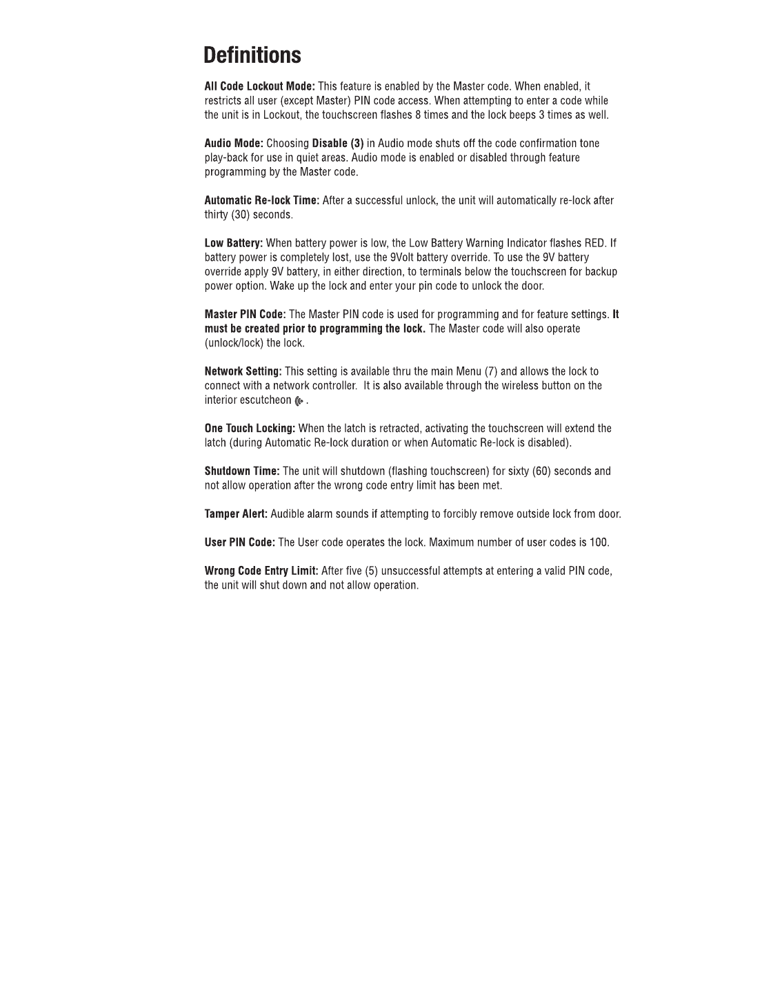
- All Code Lockout Mode: Master-enabled mode that restricts all non-Master PIN access; touchscreen flashes 8 times and beeps 3 times if a code is attempted.
- Automatic Re-lock Time: Door automatically re-locks 30 seconds after a successful unlock (if enabled).
- Low Battery: Indicator flashes RED. If batteries die completely, apply a 9V battery (either direction) to the terminals below the touchscreen for backup power, then enter your PIN to unlock.
- Shutdown Time: After 5 wrong-code attempts, the unit shuts down (flashing touchscreen) for 60 seconds.
- Tamper Alert: Audible alarm sounds if someone attempts to forcibly remove the outside lock from the door.
Troubleshooting
| Symptom | Suggested Action |
|---|---|
| Lock does not respond, door open/accessible | Check each touchscreen key responds; check battery polarity and condition; check cable is fully connected and not pinched. |
| Lock does not respond, door locked/inaccessible | Batteries may be dead — apply 9V battery to terminals below the touchscreen for backup power. |
| Code accepted (chime) but door won't open | Check for another locking device on the door, foreign objects in door gaps, and that the cable is firmly connected to the PC board. |
| Won't automatically re-lock | Check Auto Re-lock is enabled; replace batteries if low-battery indicator is lit. |
| PIN codes won't register | Codes must be 4-8 digits, unique per user, entered within 20 seconds; ✓ and ⚙ cannot be part of a PIN; contact the Master user for code management. |
| Beeps + flashes red 7 times, won't unlock | All Code Lockout Mode is enabled — only the Master can disable it. |
| No sound on operation | Enable Audio Mode (Menu 4). |
| Intermittent RED flashes | Low battery indicator — replace all 4 AA batteries. |
| Beeps + touchscreen flashes 3 times | Code entered incorrectly/incompletely — re-enter and press ✓. |
Note: When batteries are replaced, network-connected locks have a real-time clock that resets — verify date/time, especially around Daylight Saving Time changes.
Specifications & Compliance
- Model: YRD120-ZW-US (Yale Real Living T1L Touchscreen Deadbolt with Z-Wave®)
- Power: 4 AA batteries (interior compartment); 9V battery override available at terminals below the touchscreen
- FCC ID: U4A-YRIZW1US; Canadian ID: 6982A-YRIZW1US
- Complies with FCC Part 15 Class B and Industry Canada RSS/ICES license-exempt standards
- Manufacturer: Yale Security Inc., an ASSA ABLOY Group company — support: 800-810-WIRE (9473), www.yalelocks.com