
Somfy 4x ST-50 DC Motor PoE Wiring Diagram
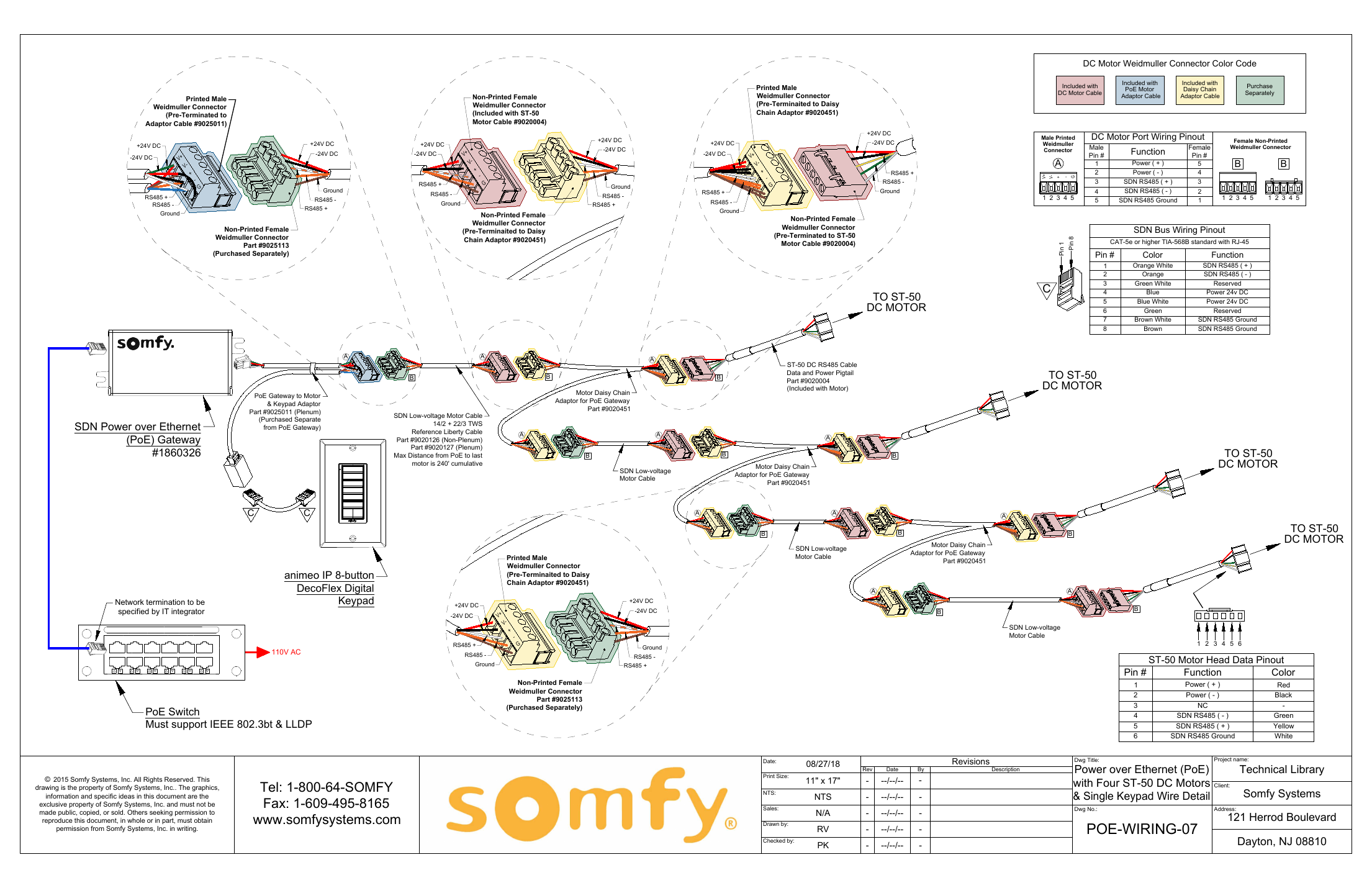
Technical wiring diagram for a Power-over-Ethernet installation with four Somfy ST-50 DC motors and a single keypad, using SDN low-voltage cabling.
Full text manual (for reference)
Technical wiring diagram for a Power-over-Ethernet (PoE) installation with four Somfy ST-50 DC motors and a single keypad, using SDN (Somfy Digital Network) low-voltage cabling. Reference drawing POE-WIRING-07.
System Overview
This diagram illustrates how a PoE Gateway distributes power and SDN RS485 data over standard network cabling to a chain of ST-50 DC motors and an animeo IP 8-button DecoFlex Digital Keypad. A PoE switch (must support IEEE 802.3bt & LLDP) feeds the PoE Gateway, which converts PoE into +24V DC power and RS485 data for the motor daisy chain.
Key Components
- SDN Power over Ethernet (PoE) Gateway (Dwg #1860326) — converts PoE input into 24V DC power + RS485 data for the SDN motor network.
- PoE Switch — must support IEEE 802.3bt and LLDP.
- PoE Gateway to Motor & Keypad Adaptor (Part #9025011, Plenum) — purchased separately, connects from the PoE Gateway.
- SDN Low-Voltage Motor Cable (14/2 + 22/3 TWS, reference: Liberty Cable Part #9020126 Non-Plenum / #9020127 Plenum) — max distance from PoE to the last motor is 240 ft cumulative.
- Motor Daisy Chain Adaptor for PoE Gateway (Part #9020451) — links each motor to the next in the chain.
- ST-50 DC RS485 Cable / Data and Power Pigtail (Part #9020004, included with motor).
- animeo IP 8-button DecoFlex Digital Keypad — 110V AC powered, terminates the SDN network (network termination specified by IT integrator).
DC Motor Port Wiring Pinout (Weidmuller Male → Female)
| Male Pin # | Function | Female Pin # |
|---|---|---|
| 1 | Power (+) | 5 |
| 2 | Power (−) | 4 |
| 3 | SDN RS485 (+) | 3 |
| 4 | SDN RS485 (−) | 2 |
| 5 | SDN RS485 Ground | 1 |
SDN Bus Wiring Pinout (CAT-5e or higher, TIA-568B, RJ-45)
| Pin # | Color | Function |
|---|---|---|
| 1 | Orange White | SDN RS485 (+) |
| 2 | Orange | SDN RS485 (−) |
| 3 | Green White | Reserved |
| 4 | Blue | Power 24V DC |
| 5 | Blue White | Power 24V DC |
| 6 | Green | Reserved |
| 7 | Brown White | SDN RS485 Ground |
| 8 | Brown | SDN RS485 Ground |
ST-50 Motor Head Data Pinout
| Pin # | Function | Color |
|---|---|---|
| 1 | Power (+) | Red |
| 2 | Power (−) | Black |
| 3 | NC | — |
| 4 | SDN RS485 (−) | Green |
| 5 | SDN RS485 (+) | Yellow |
| 6 | SDN RS485 Ground | White |
© 2015 Somfy Systems, Inc. All Rights Reserved. This drawing is the property of Somfy Systems, Inc. Dwg No. POE-WIRING-07, dated 08/27/18.