
Simply Automated USR-40A Dedicated Remote (3+ Way) Controller Base — Installation Guide
Installation guide for the Simply Automated USR-40A Series Single/Dual Dedicated Remote Controller Base, for 3-way/multi-way UPB dimming control with dual LED indication.
Full text manual (for reference)
Installation guide for the Simply Automated USR-40A Series Single/Dual Dedicated Remote Controller Base (3+ Way) — pairs with a SimplyBrilliant UPB dimmer-controller switch (US1, US2, US22 series) or fixture/receptacle modules (UFD, UFR, URD) to add remote 3-way or multi-way ON/OFF or dimming control, with dual blue/green LED status indication. Also available with an attached single white rocker as model USR1-40A-W.
⚠️ Safety Warnings:
- Installation should be performed by a qualified electrician.
- DO NOT WIRE THIS DEVICE WITH POWER CONNECTED. Injury or permanent device damage may result; improper installation voids the warranty.
- SimplyBrilliant incandescent dimmers cannot be used to dim fluorescent, electronic low-voltage, or metal halide lighting unless specifically allowed by the fixture manufacturer.
- Do not install where temperatures can exceed 120°F (e.g., an attic), and do not use outdoors.
Function
The USR-40A provides "traveler wire" connections for remote 3+way or multi-way ON/OFF/dimming control of SimplyBrilliant UPB dimming-controllers, fixture modules, and receptacle modules. It has dual (2) blue/green LED status indicators and supports a single or dual-tall rocker faceplate (models ZS11 and ZS12, in white, almond, light-almond, ivory, black, and brown).
Installation Overview
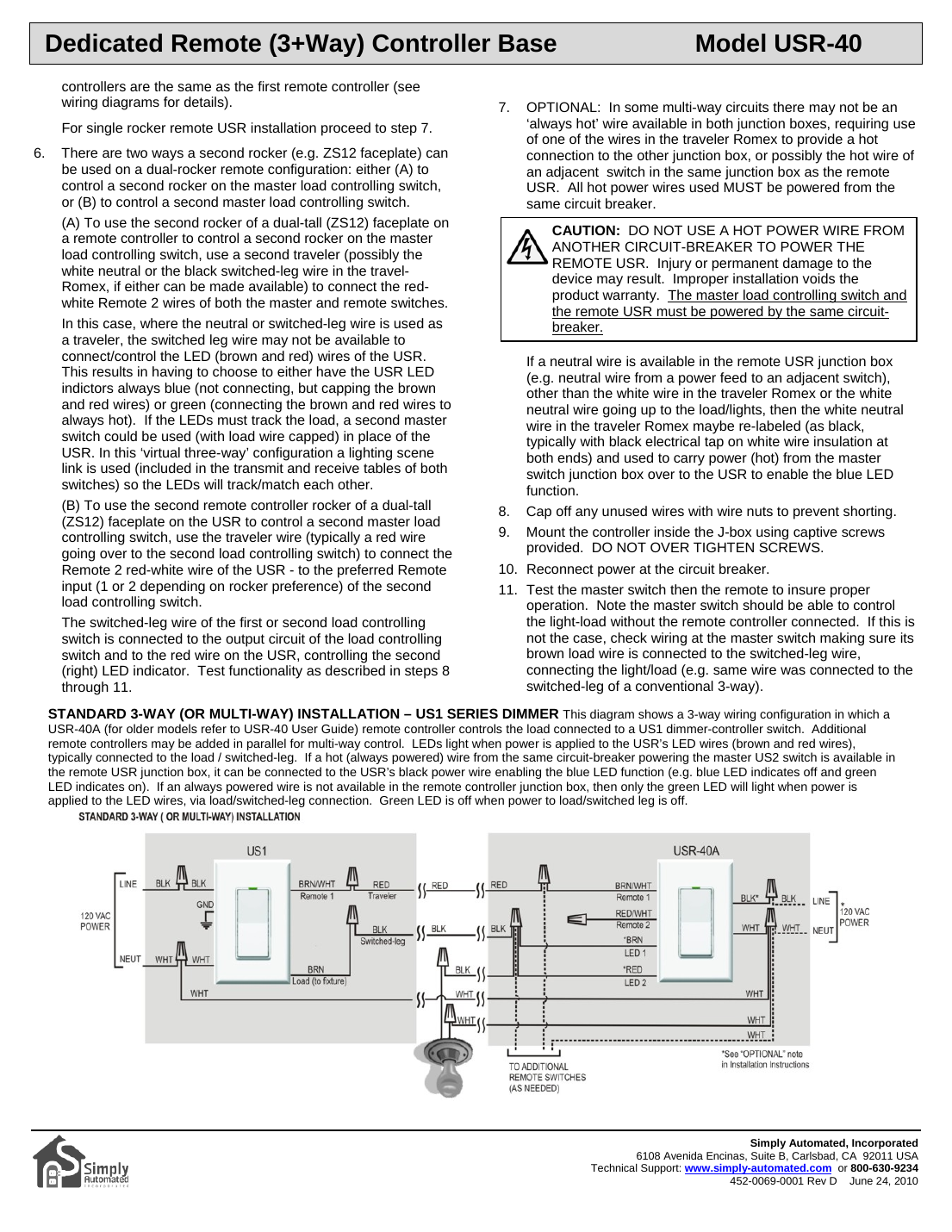
- Locate the multi-way switch junction boxes and plan where the master switch and USR remote(s) will go. Identify the "always hot" main power feed, the switched-leg load wire to the lights, and the neutral wire(s). Installing the master switch in the box with the original 3-way's main power feed is usually easiest.
- If no "always hot" wire is available at the remote USR location, only the green LED will function (unless a spare neutral wire in the traveler Romex can be re-labeled to carry power for the blue LED).
- Disconnect power at the circuit breaker before doing any wiring.
- Remove the existing switch hardware and identify the red traveler wire, black switched-leg, and white neutral wire; disconnect the old 3-way (or multi-way) switches.
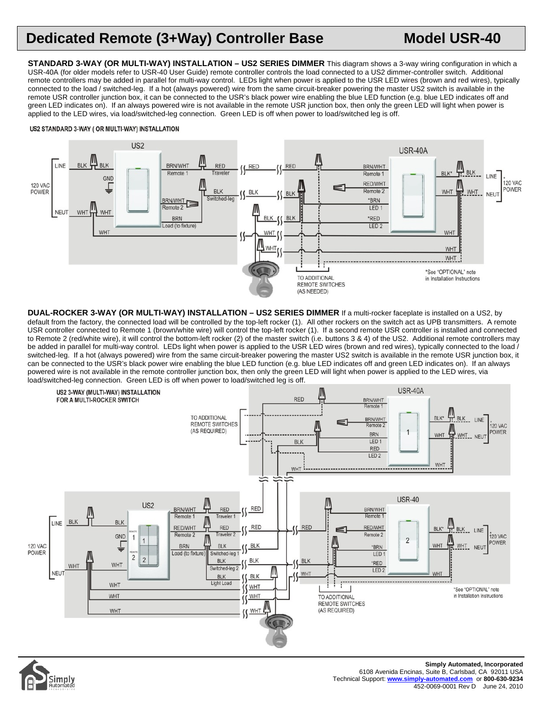
- Wire the master switch and remote USR using the traveler wire (typically red) to connect the brown-white "Remote 1" terminals on both switches. The black switched-leg wire connects to the master switch's load (brown) terminal and also drives both LED 1 and LED 2 indicators on the USR (brown and red wires respectively).
- For 4+way configurations, connect up to 6 additional USR units in parallel to the same Remote 1 traveler wire — all other connections are the same as for the first remote.
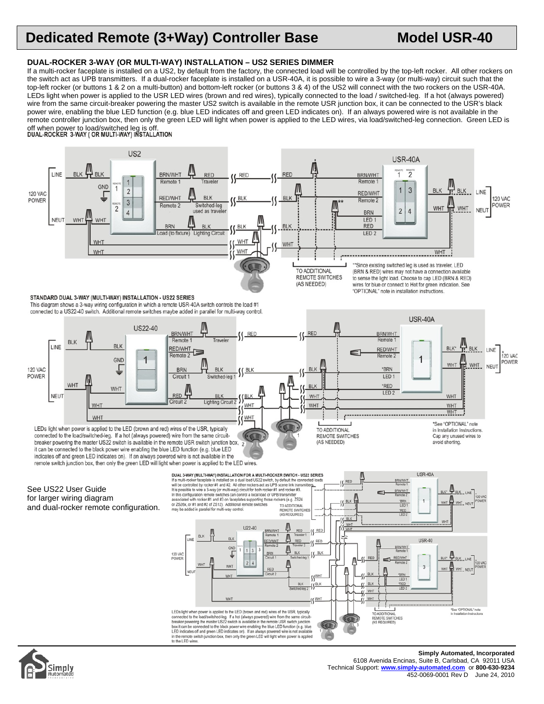
- Dual-rocker configurations: a second rocker on a USR-40A can either (A) control a second rocker on the master switch (using a second traveler wire for Remote 2), or (B) control a completely separate second master load-controlling switch. See the wiring diagrams below for the exact terminal mapping in each case.
- Optional — no "always hot" wire available: a spare traveler wire (or neutral, relabeled) can be used to carry hot power to the remote junction box to enable the blue LED — but it MUST be powered from the same circuit breaker as the master switch. Never power the remote USR from a different breaker; doing so risks injury/damage and voids the warranty.
- Cap off any unused wires with wire nuts to prevent shorting.
- Mount the controller in the J-box using the captive screws provided — do not over-tighten.
- Reconnect power at the breaker, then test the master switch and the remote to confirm proper operation (the master switch should control the load even without the remote connected — if not, recheck that the master's brown load wire is tied to the switched-leg).
Wiring Diagrams
Reference: Simply Automated, Incorporated — Document 452-0069-0001 Rev D, June 24, 2010. Technical Support: www.simply-automated.com or 800-630-9234.