
RISCO Industrial LuNAR DT AM Grade 3 — High Ceiling Mount Detector Installation Guide
Installation guide for the RISCO Industrial LuNAR DT AM Grade 3 High Ceiling Mount Detector, with Anti-Cloak Technology (ACT).
Full text manual (for reference)
Installation guide for the RISCO Industrial LuNAR DT AM Grade 3 High Ceiling Mount Detector — a dual-technology (PIR + Microwave) ceiling detector with Anti-Cloak™ Technology (ACT™), mountable up to 8.6m (28ft), certified to PD6662, EN50131-1, and TS50131-2-4 Grade 3.
Overview
The Industrial LuNAR DT AM Grade 3 combines PIR and Microwave detection with Intelligent Digital Signal Processing that automatically adjusts alarm threshold and pulse-count verification based on intruder crossing speed and environmental factors — delivering strong detection with high false-alarm immunity. It can operate as a standard relay detector on any control panel, or as an addressable BUS detector on a RISCO ProSYS panel via RS485.
Key Features
- Addressable Dual Technology detector with Anti-Cloak™ Technology
- Up to 8.6m (28ft) mounting height; 360° by 18m (60ft) diameter coverage pattern
- 3 independent PIR channels for customized coverage
- Built-in triple EOL resistors, jumper-selectable
- Active IR Anti-Masking meeting TS50131 requirements
- Ceiling and cover tampers; "Green Line" setting to disable MW when premises are occupied
- Opto-relays for low current draw and long service life
- Remote and local self-test; remote SET and RC control inputs
- PIR coverage optimization via sliding lenses; manual (trimmer) or remote microwave range adjustment
- 3 tri-color LEDs for one-person walk testing
How ACT™ (Anti-Cloak Technology) Works
Standard Dual Technology (PIR+MW) detectors have two weaknesses: IR-blocking "cloaks" that intruders can use to defeat PIR detection, and reduced PIR sensitivity when ambient temperature approaches body temperature. ACT™ solves both. It uses pattern recognition to distinguish a moving intruder's weak IR signal from background noise, and once an intruder is recognized, automatically switches from dual-channel PIR/MW mode to single-channel MW-only mode for a set period to confirm the alarm, then returns to dual-channel mode. When ambient temperature nears body temperature, ACT™ also switches to microwave-only detection to maintain sensitivity.
Under normal (non-ACT) conditions, an alarm requires both PIR and MW to trigger simultaneously, greatly reducing false alarms.
Configuration Options
| Setting | Manual (DIP/trimmer) | Remote Control Device | ProSYS BUS Control |
|---|---|---|---|
| ACT Mode | ✓ | ✓ | ✓ |
| LEDs | ✓ | ✓ | ✓ |
| MW Sensitivity | ✓ (trimmer) | ✓ | ✓ |
| Diagnostics | — | ✓ | ✓ |
| AM Diagnostics / MW Bypass / MW Disable on Disarm ("Green Line") | — | — | ✓ |
LED Display
| LED | State | Meaning |
|---|---|---|
| Red | Steady | Detector alarm (simultaneous PIR + MW) |
| Red | Flashing (low frequency) | Malfunctioned communication with ProSYS |
| Red | Flashing (high frequency) | Anti-Mask (AM) detection |
| Green | Steady | Microwave detection |
| Green | Flashing | Trouble in the MW channel |
| Orange | Steady | PIR detection |
| Orange | Flashing | Trouble in the PIR channel |
| All LEDs | Flashing, changing color | Upon power-up |
Installation Planning
- Study the protected space carefully to select the best mounting location before installing.
- Never install where the environment could cause a false alarm in one technology — avoid rotating machinery (fans) within the coverage pattern, glass exposed to the outdoors, and objects that change temperature rapidly.
- Do not mount in direct sunlight or near heat sources. Aim detection sectors at a wall or floor, not windows or curtains. The mounting surface should be solid, smooth, and vibration-free.
- Eliminate interference from nearby outside sources.
- Recommended mounting height for full 18m (60ft) detection: 3.7m to 8.6m. Mount on the ceiling, preferably near the center of the room. Below 3.7m, coverage diameter decreases (down to 15m/50ft at 2.7m).
Installation Process
- Remove the detector's protection cap and cover by inserting a screwdriver into the recess between the cap and cover (the cover stays attached to the base).
- Release the upper cover screw with a Phillips screwdriver and gently pull the upper cover upward.
- Release the PCB holding screw on the right side of the board, pull the two release clips outward, and remove the PCB. Do not touch the PIR sensors.
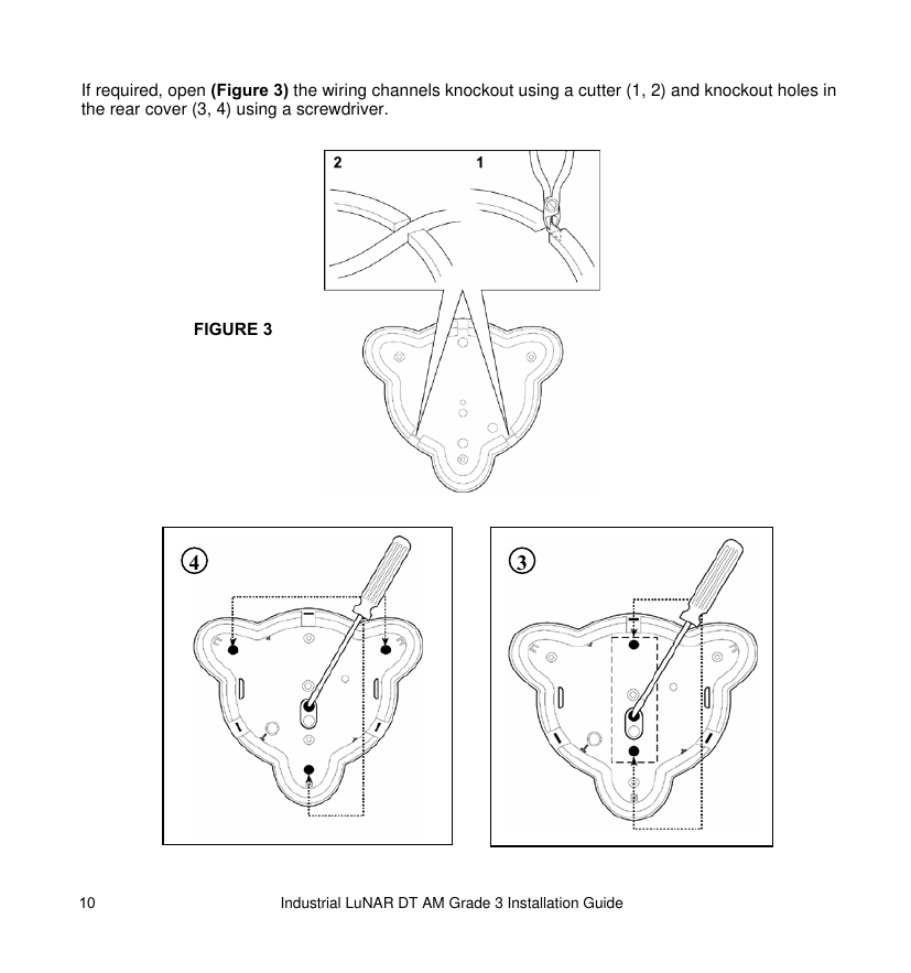
- If needed, open the wiring channel knockouts (using a cutter) and the rear cover knockout holes (using a screwdriver) — see Figure 3 above.
- Insert the cable through the cable opening and wire per the Terminal Blocks section below.
- Mount the rear cover in its final location using the 3 mounting screws, and seal any remaining open knockout holes with sealant.
- Return the PCB to its original position, confirming it's secured by the holding clips and screw.
- Perform lens adjustment and DIP switch settings (see below).
- Mount the top cover on the base, tighten the central screw, and replace the protection cap.
If using a single-gang box, add 2 extra screws to mount the base — but note the back tamper cannot be used in that configuration. To enable a ceiling tamper, break open the ceiling tamper hole in the detector's base.
Lens Adjustment
The LuNAR has three Fresnel lenses in protective sleeves on the cover. To adjust for your mounting height:
- Press the 2 clips attaching the sleeve to the cover and gently pull the sleeve out.
- Remove the lens from the sleeve by lifting it off the holding pins on its sides.
- Place the sleeve's two side pins into the matching slots on the lens at the desired position for your mounting height.
- Return the sleeve to the front cover.
- Repeat for the remaining 2 lenses.
Each lens has 4 adjustable positions. For customized coverage, each of the 3 lenses can be set to a different height/position based on installation conditions. Avoid touching the PIR sensors during this process.
DIP Switch Settings
The detector has a 9-position DIP switch. Switch 6 selects the overall mode: OFF = Relay Mode, ON = BUS Mode (ProSYS).
Relay Mode (DIP 6 = OFF)
| DIP | Function |
|---|---|
| 1 | ACT: On = enabled; Off = disabled (default) |
| 2 | LEDs: On = enabled (default); Off = disabled |
| 3 | "Green Line": On = enabled; Off = disabled (default) |
| 4 | Self Test type: On = Local (FAULT/AM relay activates 2.5 sec on failure); Off = Remote (default — Alarm relay activates 5 sec on pass, FAULT/AM relay 2.5 sec on failure) |
| 5 | Active IR Anti-Masking: On = enabled; Off = disabled (default). If enabled, the cover must be fitted within 1 minute of power-up, or the unit must be power-cycled to reset AM calibration. |
| 6 | Connection mode: Off = Relay mode |
| 7 | Remote Control (RC): On = RC always enabled; Off = RC depends on terminal block voltage (default). Turn OFF after installation to prevent unauthorized remote-control access. |
| 8-9 | Off (see Terminal Blocks for related activation) |
BUS Mode (DIP 6 = ON)
| DIP | Function |
|---|---|
| 1-5 | Detector BUS ID number (01-32), set per the standard ProSYS ID binary pattern |
| 6 | On = ProSYS BUS connection mode |
| 7 | Not applicable (RC auto-enabled during ProSYS Walk Test mode only) |
| 8-9 | On = report tamper status to ProSYS |
On power-up, the LuNAR waits 10 seconds for ProSYS communication in BUS mode. If Red LEDs flash continuously, check wiring, address configuration, and ProSYS setup.
EOL Resistor Jumpers
Used when connecting to a DEOL or TEOL zone. Jumpers select TAMPER and ALARM EOL resistor values (1K, 2.2K, 4.7K, 5.6K, or 6.8K) to match your control panel. A separate double jumper selects a 12K FAULT/AM EOL resistor (default: no resistor).
Terminal Blocks
Terminal Block 1
| +12V (RED) | Power supply positive input |
| - (BLK) | Common to control panel power supply |
| BUS (GRN) / BUS (YEL) | Data communication with ProSYS |
| SET | Remote SET/UNSET. When activated: disables AM (if DIP5 was on) and enables the MW module (if Green Line DIP3 was on). Removing the signal triggers a self test (if Remote Self Test DIP4 was off). Not relevant in BUS mode. |
| RC (Remote Control) | Enables/disables remote control communication when DIP7 is OFF. Not relevant in BUS mode. |
Terminal Block 2
| AM/FAULT | N.C. output; opens when masked (Alarm also opens), self-test fails, or input voltage is low (6-8VDC) |
| TAMPER | N.C. output |
| ALARM | N.C. output |
Walk Test
- Enable the LEDs first.
- Two minutes after power-up (warm-up period), walk the entire protected area and observe the tri-color LED. The edge of the microwave pattern is marked by the first red LED activation (both PIR and MW triggered).
- If PIR/MW LEDs don't turn on, check lens position (PIR) or MW adjustment.
- Adjust microwave sensitivity via the PCB potentiometer or Remote Control device — set to the lowest setting that still covers the entire protected area.
- When using the Remote Control device, run the LuNAR Self Test per its instructions.
Important: turn DIP switch 7 "OFF" after installation and when leaving the site, to prevent unauthorized remote-control access.
Troubleshooting
| Trouble | Meaning | Response |
|---|---|---|
| ProSYS configuration of detectors fails/not accepted | ID configuration problem | Disconnect power, configure desired IDs, reconnect power |
| Tamper indication while in BUS mode | Tamper connection malfunction | Verify DIP 8 and 9 are both ON |
| Tamper indication in Relay or BUS mode | Tamper probably not closed | Visually verify the ceiling tamper and spring are correctly installed |
| Walk test cannot be initiated via ProSYS keypad | Wrong code | Insert the appropriate code |
| Green LED doesn't operate during walk test — MW doesn't function | Configured for "MW disable on Disarm" during ProSYS DISARM mode | Normal behavior |
| Same symptom, but caused by "Bypass MW channel" mode | MW channel trouble | Reset the detector; replace it if the trouble recurs |
Specifications
| Coverage | 192 fingers (96 Fresnel facets) across 3 lens sections, each with 4 adjustable positions; 360° x 18m (60ft) diameter (decreasing to 15m/50ft below 3.7m mounting height) |
| Variable mounting height | 2.7m to 8.6m (9' to 28'), 4 lens positions |
| RFI immunity | 40 V/m from 10MHz to 1GHz |
| Operating voltage | 9 to 16 VDC |
| Current consumption | 20mA at 12VDC; 30mA at 16VDC; max 40mA with all LEDs on |
| Alarm and AM contacts | Opto-relay N.C., 100mA, 24VDC |
| Tamper contacts | N.C., 500mA, 24VDC |
| Alarm time | 2.2 seconds |
| Warm-up time | 2 minutes |
| Optical filtering | Pigmented Fresnel lens (white light protection) |
| Operating temperature | -20°C to 55°C (-4°F to 131°F) |
| Storage temperature | -20°C to 60°C (-4°F to 140°F) |
| Dimensions (H x Diameter) | 99mm x 194mm (3.9" x 7.6") |
Certified for installations complying with PD6662, EN50131-1, and TS50131-2-4 Grade 3, Class II.
Ordering Information
| Part Number | Description |
|---|---|
| RK200DTG300A | Industrial LuNAR DT AM Grade 3 Detector, 10.525GHz |
| RK200DTG3UKA | Industrial LuNAR DT AM Grade 3 Detector, 10.687GHz |
| RK200DTG3FRA | Industrial LuNAR DT AM Grade 3 Detector, 9.9GHz |
| RK200DTG3DEA | Industrial LuNAR DT AM Grade 3 Detector, 9.35GHz |