
PulseWorx SPR-1/SPR-4 — Split-Phase Repeater Installation Guide
Installation guide and owner's manual for the PulseWorx SPR-1/SPR-4 Split-Phase Repeaters — active UPB devices that boost powerline communication across split-phase circuits.
Full text manual (for reference)
Installation guide and owner's manual for the PulseWorx SPR-1 and SPR-4 Split-Phase Repeaters — active UPB devices that boost powerline communication reliability across the two phases (legs) of a residential 120/240VAC split-phase electrical system.
Function
The Split-Phase Repeater is designed to enhance communication reliability between UPB (Universal Powerline Bus) devices, such as PulseWorx products. It works by taking UPB messages transmitted on one phase and strongly repeating them onto the other phase, using patented Dual Cap transmitter technology. The repeated signal is boosted to 150% of the received signal strength.
- SPR-1: Wire-in model — installs in a junction box and wires directly to two phases (circuits) and neutral at the circuit breaker panel.
- SPR-4: Plug-in model — plugs into any 4-socket NEMA 14-30 240V electrical outlet.
The SPR works best when plugged or wired in as close to the main circuit breaker panel as possible.
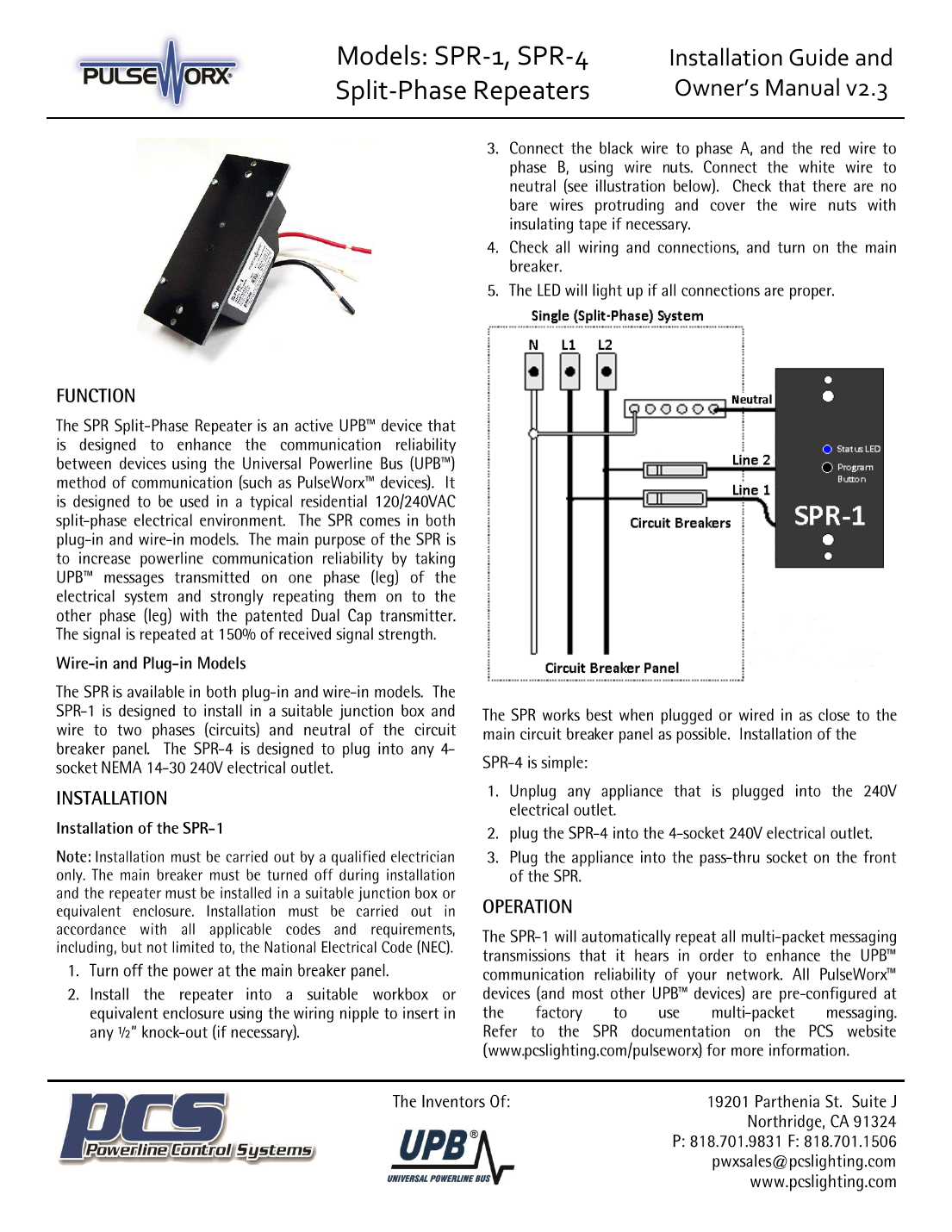
Wiring Diagram — SPR-1 Split-Phase Installation
Installation — SPR-1 (Wire-In)
Must be installed by a qualified electrician only. Installation must comply with all applicable codes, including the National Electrical Code (NEC).
- Turn off power at the main breaker panel.
- Install the repeater into a suitable junction box or equivalent enclosure, using the wiring nipple to insert into a ½" knockout if necessary.
- Connect the black wire to Phase A and the red wire to Phase B using wire nuts. Connect the white wire to neutral. Ensure no bare wires are exposed — cover wire nuts with insulating tape if necessary.
- Check all wiring and connections, then turn the main breaker back on.
- The LED lights up if all connections are proper.
Installation — SPR-4 (Plug-In)
- Unplug any appliance currently plugged into the 240V outlet.
- Plug the SPR-4 into the 4-socket 240V electrical outlet.
- Plug the appliance into the pass-through socket on the front of the SPR-4.
Operation
The SPR automatically repeats all multi-packet messaging transmissions it hears, enhancing UPB communication reliability across the network. PulseWorx devices (and most UPB devices) are factory-configured to use multi-packet messaging by default.
Configuration (UPStart Software)
The SPR-1 will operate without configuration, but it's highly recommended to add it to your UPB network using PCS's UPStart Setup Software with a Unit ID. Once added, UPStart can adjust receive sensitivity and run communication tests to confirm proper signal strength.
Adding the SPR-1 to a UPStart Network
- In UPStart, select Device → Add Device.
- Put the SPR into Setup Mode: tap the Program Button 5 times. The Status LED blinks blue to confirm Setup Mode.
- Click Next, then assign a Room and Device Name for identification.
- Exit Setup Mode by double-tapping the Program Button.
Communication Tests
UPStart's Repeater Communication Test measures how well each device communicates to the SPR and how well the SPR communicates to all devices — recording signal strength, noise level, and phase at each device. Run this after installation and after any receive sensitivity change.
Adjusting Receive Sensitivity
Receive sensitivity is adjustable between LOW and HIGH (LOW helps block powerline noise). This can be set via UPStart, or manually via the Program Button:
- Press and hold the Program Button for 5 seconds, then release. The Status LED blinks red once (LOW) or twice (HIGH) to show the current setting.
- Single-tap the Program Button to select LOW, or double-tap to select HIGH.
- Press and hold the Program Button for 5 seconds to save the new setting, then release — the Status LED returns to blue.
Other Things You Should Know
- Multi-packet messaging: The SPR repeats multi-packet transmissions only — it will NOT repeat uni-packet (Gen 1) transmissions. PulseWorx and most UPB devices default to 2-time multi-packet messaging.
- UPStart behavior: UPStart normally uses uni-packet transmissions, but automatically switches to multi-packet once an SPR is added to the network — shown as "TX=2" in the status bar, alongside whether the PIM is on the Same or Opposite phase. UPStart's Network Discovery function can quickly identify Unit IDs in use; in large electrical environments it must use the SPR to reach devices on all phases.
- Status LED colors: Red = SPR transmitting; Purple = SPR receiving; Blue = idle (nothing happening on the powerline).
- Multiple SPR-1 units: If more than one SPR-1 is installed on a single electrical system, change multi-packet messaging to 3-time (3-time multi-packets) across the network.
Warranty
Seller warrants this product, when used per all applicable instructions, to be free from original defects in materials and workmanship for five years from date of purchase. See the PulseWorx website for full details.
Manufacturer
PCS Powerline Control Systems — 19201 Parthenia St. Suite J, Northridge, CA 91324. Phone: 818-701-9831. Fax: 818-701-1506. Email: pwxsales@pcslighting.com. Web: www.pcslighting.com.