
Optex LX-402 & LX-802N — Outdoor PIR Detector Installation Manual
Installation manual for the Optex LX-402 (120° wide-angle) and LX-802N (long-range) outdoor PIR detectors.
Full text manual (for reference)
Installation manual for the OPTEX LX-402 and LX-802N outdoor Passive Infrared (PIR) detectors — the LX-402 is a 120° wide-angle detector with 40ft (12m) range; the LX-802N is a long-range detector with 80ft (24m) range. Both are IP54-rated, weatherproof outdoor motion detectors with a Form C relay output and tamper switch.
Key Features
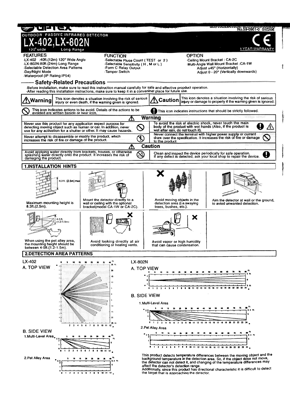
- Selectable detection area patterns (Multi-Level or Pet Alley)
- Day/Night mode adjustment
- Waterproof — IP54 rated
- Selectable pulse count (Standard "2" or "TEST" mode)
- Selectable sensitivity: High (H), Medium (M), Low (L)
- Form C relay output (NC/NO switchable) plus tamper switch
- Optional Ceiling Mount Bracket (CA-2C) and Multi-Angle Wall Mount Bracket (CA-1W), both adjustable ±45° horizontal / 0–20° vertical downward
Installation Guidance
- Maximum mounting height: 8.3 ft (2.5m) for standard Multi-Level detection
- Pet Alley mounting height: 4–5 ft (1.2–1.5m)
- Avoid aiming the detector at moving foliage/trees, A/C or heating vents, or areas with vapor/humidity that can cause condensation
- Aim the detector at a wall or the ground where possible to avoid false detection from unwanted movement
Component Parts
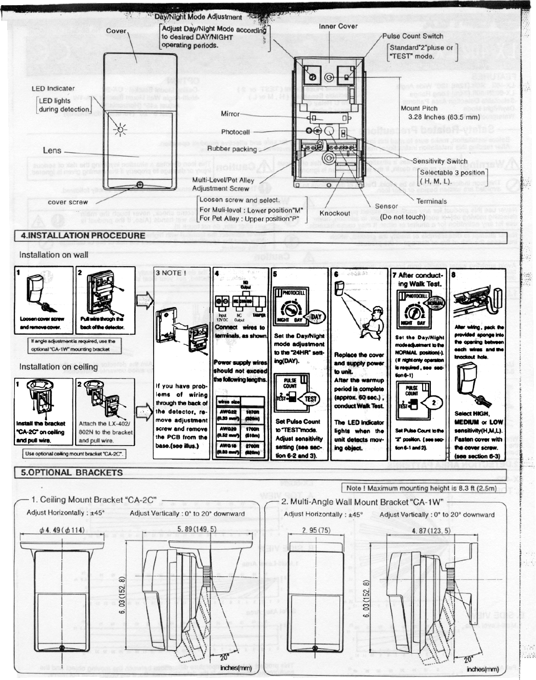
Cover, LED indicator, lens, cover screw, inner cover, mirror, photocell, rubber packing, Multi-Level/Pet Alley adjustment screw, pulse count switch (Standard "2" or "TEST"), sensitivity switch (H/M/L), sensor (do not touch), wiring terminals, and knockout. Mount pitch: 3.28" (83.5mm).
Installation Procedure — Wall Mount
- Loosen the cover screw and remove the cover.
- Route wiring through the knockout.
- Connect wires to the terminals: 12V DC Input, NC/NO Output, and Tamper.
- Set Day/Night mode to 24HR (DAY) for initial testing.
- Replace the cover.
- Conduct a walk test.
- Set the Pulse Count switch to "2" for normal operation.
- Adjust sensitivity as needed, then pack sponge into the wire opening.
Ceiling installation (using the optional CA-2C bracket) is a simplified 2-step process — see the full PDF for bracket-specific instructions.
Wire Size / Maximum Run Length
| Wire Gauge | Cross Section | Max. Run Length |
|---|---|---|
| AWG22 | 0.33mm² | 1070 ft (320m) |
| AWG20 | 0.52mm² | 1700 ft (510m) |
| AWG18 | 0.83mm² | 2700 ft (820m) |
Optional Mounting Brackets
- CA-2C Ceiling Mount Bracket: 4.49" (114mm) diameter, 5.89" (149.5mm) depth, 6.03" (152.8mm) height; adjustable ±45° horizontal, 0–20° vertical
- CA-1W Multi-Angle Wall Mount Bracket: 2.95" (75mm) width, 4.87" (123.5mm) length, 6.03" (152.8mm) height; adjustable ±45° horizontal, 0–20° vertical downward
Switch & Mode Settings
- Day/Night Mode: Dial adjustment between NIGHT and DAY positions. Preset at "NORMAL" (dusk/night operation only); shifting toward DAY allows earlier activation, toward NIGHT allows later activation, and full DAY allows constant/testing operation.
- Pulse Count Switch: "2" (standard, pre-set, normal use) vs. "TEST" (for walk tests or unstable environments).
- Sensitivity Switch: M (standard/normal, pre-set), H (high — e.g. Pet Alley mode), L (for unstable/noisy environments).
Detection Area Adjustment
- Multi-Level vs. Pet Alley: Loosen the screw, slide the cover, and flip the mirror to the "P" position to switch to Pet Alley mode. Sensitivity must also be raised one step when switching to Pet Alley — both changes are required for correct pet-alley operation.
- Eliminating unwanted detection zones (LX-402 only): Apply masking strips to the inside of the lens, targeting specific labeled zones (a–k) to block out unwanted detection areas.
Troubleshooting
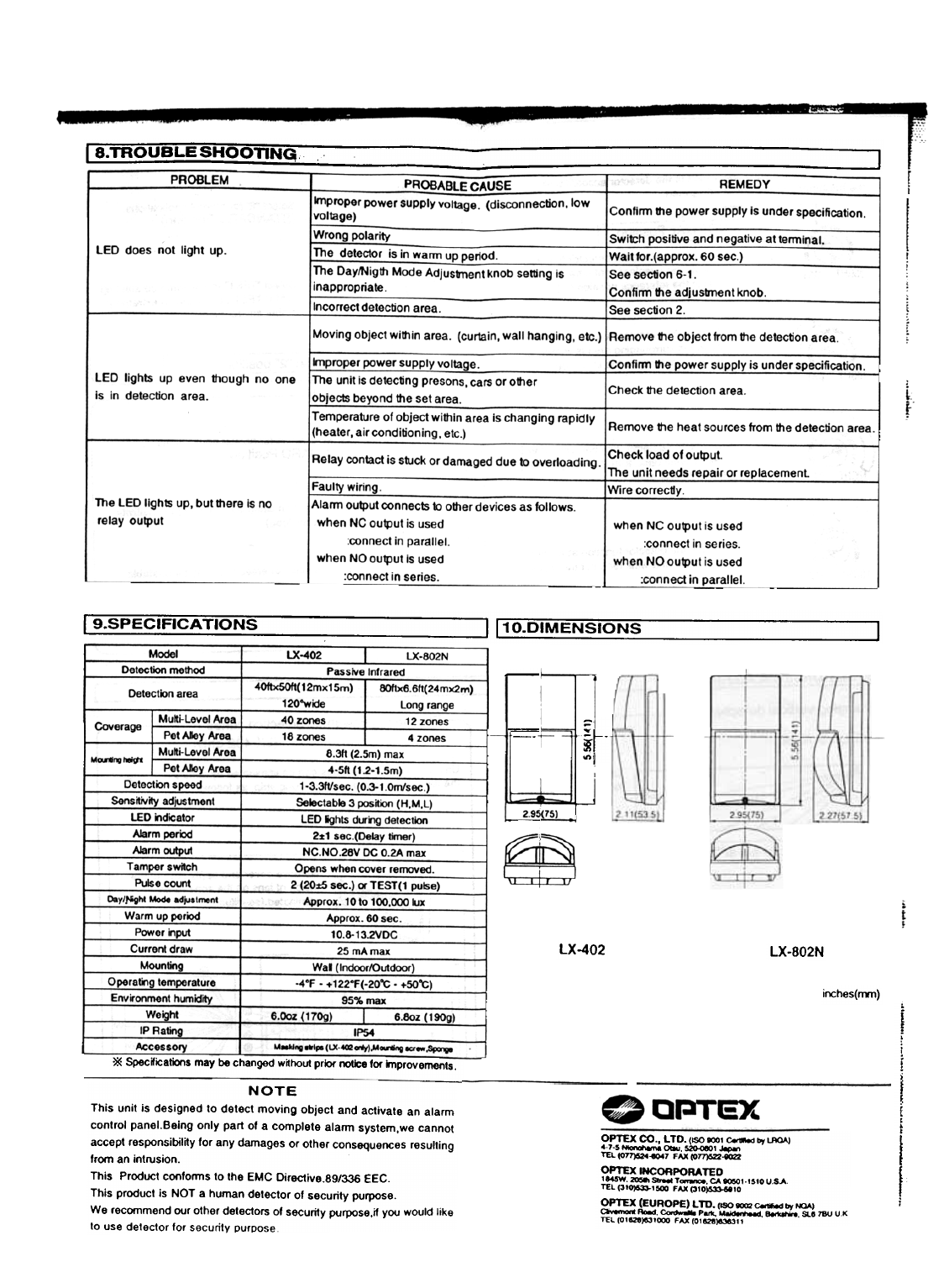
| Problem | Probable Cause | Remedy |
|---|---|---|
| LED not lighting | Wrong polarity or wiring issue; unit still within warm-up period | Check wiring polarity and connections; allow the ~60 second warm-up period to complete |
| False triggering | Incorrect detection area, heat sources in the field of view | Adjust detection area / mask unwanted zones, or relocate away from heat sources |
| No relay output | Relay contact damage or incorrect NC/NO wiring configuration | Verify wiring matches parallel vs. series connection requirements for your NC/NO setup; replace unit if relay contacts are damaged |
Specifications
| Parameter | LX-402 | LX-802N |
|---|---|---|
| Detection method | Passive Infrared | Passive Infrared |
| Detection area | 40ft x 50ft (12m x 15m), 120° wide | 80ft x 6.6ft (24m x 2m), long range |
| Multi-Level coverage | 40 zones | 12 zones |
| Pet Alley coverage | 16 zones | 4 zones |
| Mounting height | 8.3ft (2.5m) max (Multi-Level); 4-5ft (1.2-1.5m) (Pet Alley) | |
| Detection speed | 1–3.3 ft/sec (0.3–1.0 m/sec) | |
| Sensitivity adjustment | 3-position (H, M, L) | |
| Alarm period | 2 ± 1 sec (delay timer) | |
| Alarm output | NC, NO — 28V DC, 0.2A max | |
| Tamper switch | Opens when cover is removed | |
| Pulse count | 2 (20 ± 5 sec) or TEST (1 pulse) | |
| Day/Night adjustment range | Approx. 10 – 100,000 lux | |
| Warm-up period | Approx. 60 sec | |
| Power input | 10.8 – 13.2 VDC | |
| Current draw | 25mA max | |
| Operating temperature | -4°F to +122°F (-20°C to +50°C) | |
| Humidity | 95% max | |
| Weight | 6.0 oz (170g) | 6.8 oz (190g) |
| IP Rating | IP54 | |
| Included accessories | Masking strips, mounting screw, sponge | Mounting screw, sponge |
Warranty
1-Year Limited Warranty. CE marked.
Manufacturer
OPTEX CO., LTD. (Japan, ISO 9001 certified) — OPTEX INCORPORATED (Torrance, CA, USA) — OPTEX (EUROPE) LTD. (Maidenhead, Berkshire, UK). This unit is not intended as a stand-alone security device and complies with EMC Directive 89/336/EEC.