
OEM Systems MS-21-IK Installation Kit — Quick Reference
Quick reference for the OEM Systems MS-21-IK Installation Kit, used to mount the MS-21 Mainstation between wall studs during new-construction or retrofit installation.
Full text manual (for reference)
Quick reference for the OEM Systems MS-21-IK Installation Kit, used to mount the MS-21 Mainstation between wall studs during new-construction or retrofit installation.
Overview
The MS-21-IK kit provides an adjustable installation frame and power supply mounting hardware for the MS-21 Mainstation. It supports both new-construction and retrofit installations. If installation is beyond your qualifications, hire a licensed electrician to run electrical cables and perform AC mains connections.
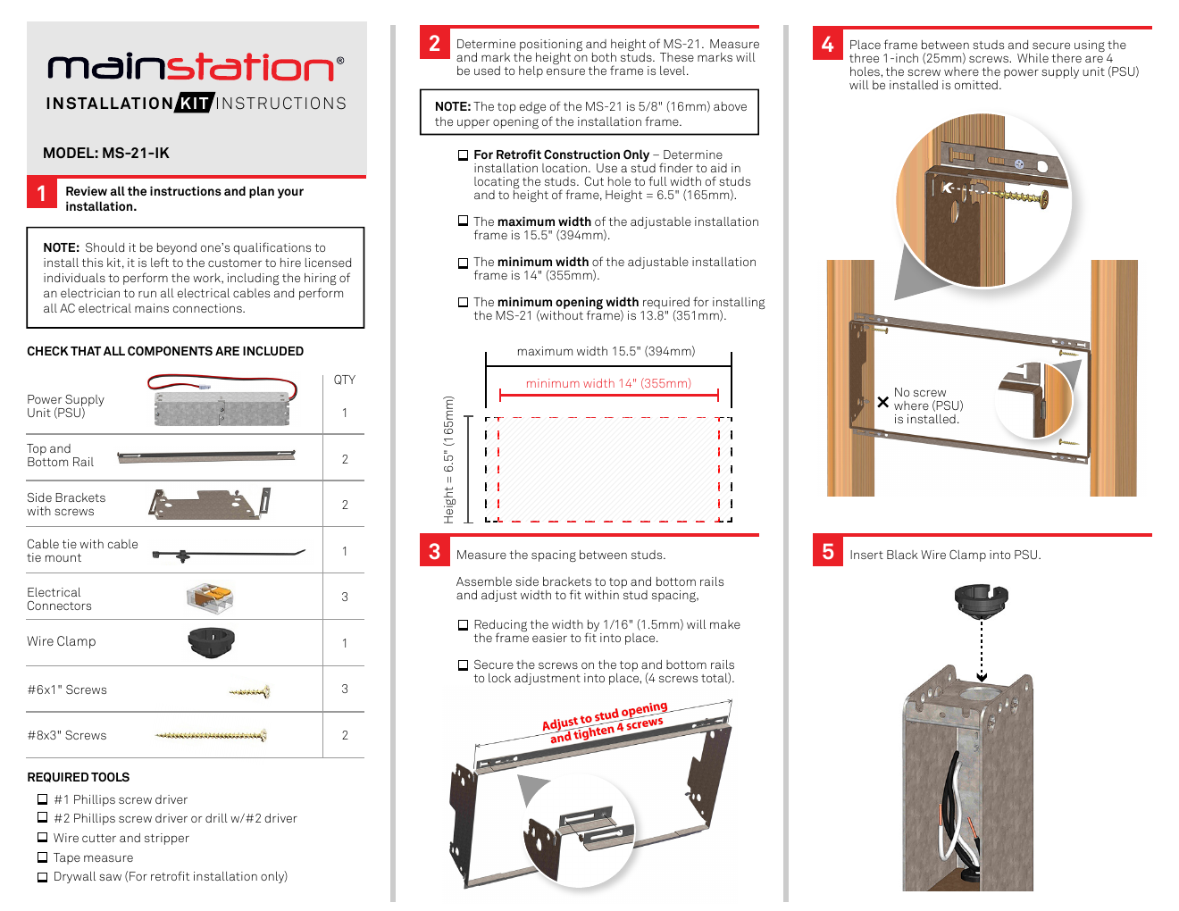
What's Included
- Power Supply Unit (PSU) — 1
- Top and Bottom Rail — 2
- Side Brackets with screws — 2
- Cable tie with cable tie mount — 1
- Electrical Connectors — 3
- Wire Clamp — 1
- #6 x 1" Screws — 3
- #8 x 3" Screws — 2
Required Tools
- #1 Phillips screwdriver
- #2 Phillips screwdriver or drill w/#2 driver
- Wire cutter and stripper
- Tape measure
- Drywall saw (retrofit installation only)
Frame Dimensions
- Maximum installation frame width: 15.5" (394mm)
- Minimum installation frame width: 14" (355mm)
- Minimum opening width required (without frame): 13.8" (351mm)
- Frame height: 6.5" (165mm)
- Top edge of MS-21 sits 5/8" (16mm) above the upper opening of the installation frame
Installation Overview
- Review all instructions and plan the installation.
- Determine positioning and height of the MS-21; mark the height on both studs to keep the frame level. For retrofit construction, locate studs with a stud finder and cut the hole to the full width of the studs and to frame height (6.5").
- Measure the spacing between studs; assemble side brackets to the top and bottom rails and adjust the width to fit within the stud spacing (reducing width by 1/16" makes the frame easier to fit). Lock the adjustment in place with all 4 screws.
- Place the frame between the studs and secure it with three 1" screws (the 4th hole, where the PSU mounts, is left unscrewed).
- Insert the black wire clamp into the PSU.
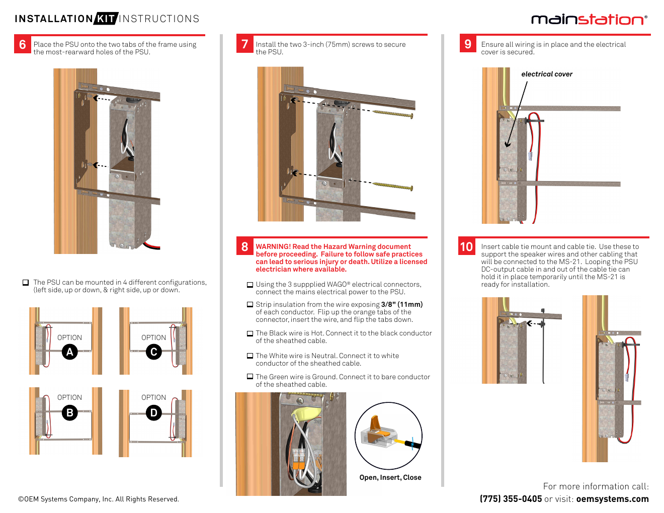
- Place the PSU onto the two rearmost tabs of the frame.
- Secure the PSU with two 3" screws. The PSU can be mounted in 4 configurations (left side up/down, right side up/down) — see the diagram below.
- WARNING: Read the Hazard Warning document before proceeding — failure to follow safe practices can lead to serious injury or death. Use a licensed electrician where required. Using the 3 supplied WAGO® electrical connectors, connect mains power to the PSU: strip 3/8" (11mm) of insulation from each conductor, flip up the orange tab, insert the wire, and flip the tab back down. Black = Hot, White = Neutral, Green = Ground (bare conductor).
- Confirm all wiring is in place and the electrical cover is secured.
- Insert the cable tie mount and cable tie to support speaker wires and other cabling connected to the MS-21. Looping the PSU's DC-output cable through the tie can hold it temporarily until the MS-21 is ready for final installation.
Manufacturer
OEM Systems Company, Inc. — (775) 355-0405 or oemsystems.com