
Menu
-
-
Home Automation
- Home Automation Controllers
- Lighting & Appliance Controls
- Home Automation Sensors
-
Ventilation, Temperature & Flood Controls
- Ecovent Ventilation Controls
- Keen Home Ventilation Controls
- La Crosse Weather Reporting System
- Sensaphone Temperature/Flood
- Winland Temperature/Flood Reporting
- Ezlo Water/Flood Detection
- WaterBug Water/Flood Detection
- WaterCop Water/Flood Detection
- Specialty Water/Flood Detection
- Temperature & Heat Sensors
- Smart Irrigation Controllers
- Smart Thermostats & Ventilation Controls
- Drapery & Blind Opener Systems
- Window Opener Systems
- Door & Gate Opener Systems
- Garage Remotes & Controllers
- Smart Door Locks
-
Security
-
Home Intercom Systems
-
Specials
-
Audio/Video
-
Independent Living
-
Structured Wiring
-
More...
-
Our Brands
- 2GIG
- A&D Medical
- ABB
- Adorne
- Advanced Dynamics
- Aeotec
- Alfred
- American Hunter
- Applied Digital (ADI)
- AprilAire
- Aria Audio Technology
- Arlington Industries
- Applied Digital (ADI)
- AprilAire
- BackBoxx™
- Bellman & Symfon
- BlueSpray
- Cabletronix
- Caregiver Smart Home Automation
- Chamberlain
- Chief Manufacturing
- Cool Components
- Dakota Alert
- Danalock
- DataComm
- Data-Tronix
- D+H
- Displine
- DoorBell Fon
- DynaQuip Controls - Watercop
- Ecovent
- Elk Products
- Enbrighten
- Evolve Technologies
- Ezlo
- FirstAlert
- Flipper
- Flic
- GE
- GoControl
- Go Simply Connect
- Greenfield Direct
- Hamilton CapTel
- Home Controls In-House Exclusives
- HomeSeer
- Honeywell Home
- ION Digital
- Inovonics Wireless
- Interstate Batteries
- Intrasonic Technology (IST)
- Jasco
- KBSound
- Keen Home
- Kwikset
- La Crosse Alerts
- Letzgo Products
- Leviton
- Linear
- Linxura
- Lithe Audio
- Luxul
- Mail Chime
- MedReady
- myTouchSmart
- Napco Security Systems
- NETIO
- Nice North America
- NuTone
- OEM Systems Co.
- Presence Speakers
- On-Q By Legrand
- Open Sesame
- Optex
- Platinum Tools
- Powerline Control Systems
- Qolsys
- Resideo
- Risco Group
- Russound
- RYSE
- STI
- Sanus
- Satco
- Seco-Larm
- Security Door Controls (SDC)
- Sensaphone
- Sensative
- Serene Innovations
- Shelly
- Simply Automated, Inc. (SAI)
- Skylink
- Somfy Systems
- Sonic Alert
- Speco Technologies
- Stelpro
- Street Smart Security
- Structured Cable Products (SCP)
- TekTone
- Tripp Lite
- Truth Hardware
- U-Tec
- UCS
- USP
- Vera
- Versa
- VMP - Video Mount Products
- VSSL
- WeBoost
- Winland Electronics
- X10
- Yale
- ZTECH
- Shop By Compatibility
- Home Essentials
- Central Vac
-
Our Brands
-
- Orders
- Profile
- 1-858-693-8887
- Login
-
United States (USD $)
Add description, images, menus and links to your mega menu
A column with no settings can be used as a spacer
Link to your collections, sales and even external links
Add up to five columns
Add description, images, menus and links to your mega menu
A column with no settings can be used as a spacer
Link to your collections, sales and even external links
Add up to five columns
NAPCO FireWolf FW-4 / FW-2 Photoelectric Smoke Detectors — Installation & Wiring Instructions
August 31, 2026 2 min read
Installation and wiring instructions for the NAPCO FireWolf™ FW-4 and FW-2 2-wire photoelectric smoke detectors, including wiring diagrams and cleaning/maintenance procedures.
Full text manual (for reference)
Quick reference guide for the NAPCO FireWolf™ FW-4 and FW-2 photoelectric smoke detectors. This manual is fully diagram-based (wiring diagrams and exploded-view illustrations); the images below and the full downloadable PDF cover complete installation, wiring, and cleaning procedures.
Overview
The FireWolf FW-4 and FW-2 are 2-wire photoelectric smoke detectors designed for compatibility with UL Listed control panels, including NAPCO GEM-P3200, GEM-P9600, and Express XP600 series panels. Both models operate on 8-35VDC and mount to standard 3" or 4" octagon boxes using the included trim ring.
Wiring & Installation
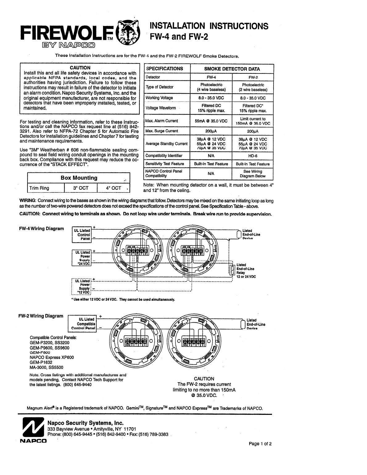
Caution: Wiring must meet supervision requirements and current-limiting specifications per the control panel manufacturer's installation instructions.
Mounting, Testing & Service
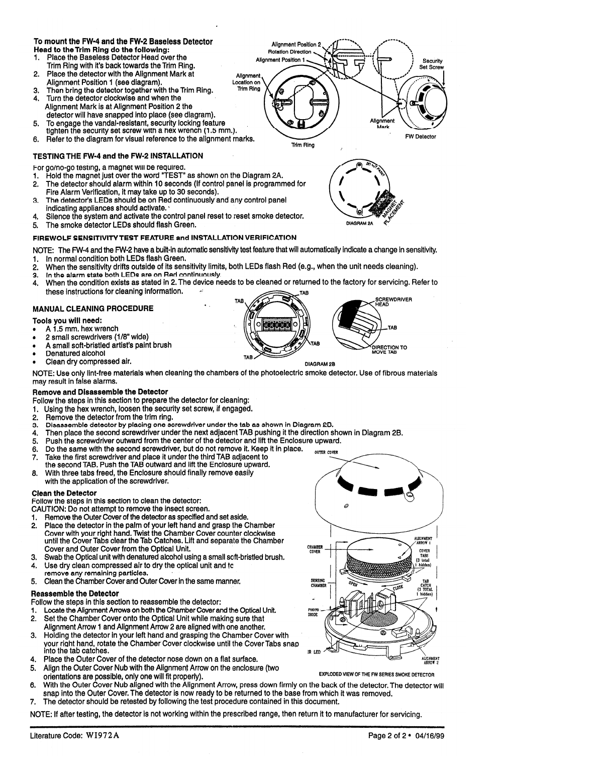
Installation Steps (Summary)
- Mount the trim ring to a 3" or 4" octagon box per the box mounting table.
- Wire the detector base in series with other detectors, connecting to the control panel per the polarity (+/-) shown in the wiring diagram.
- Align the detector head with the trim ring alignment marks and rotate to lock in place, securing with the tamper set screw.
- Test using the go/no-go magnet over the "TEST" label (Diagram 2A).
Cleaning & Maintenance
- To remove the cover for cleaning, use two screwdrivers under the tabs as shown in Diagram 2B.
- Clean the sensing chamber, photodiode, and IR LED area using denatured alcohol and a soft brush.
- Reassemble by aligning the cover tabs and catches, then reattach the outer cover.
Compatible Control Panels (FW-2)
GEM-P3200, GEM-P9600, NAPCO Express XP600, and other UL Listed compatible panels — see the full wiring diagram for the complete compatibility list.
Subscribe
Sign up to get the latest on sales, new releases and more …