
NAPCO C-100STE / C-100STLRE — Dual-Technology Motion Sensor Installation Instructions
Installation instructions for the NAPCO C-100STE / C-100STLRE Dual-Technology PIR/Microwave Motion Sensor.
Full text manual (for reference)
Installation instructions for the NAPCO C-100STE / C-100STLRE Dual-Technology PIR/Microwave Motion Sensor — an intrusion detector combining passive infrared and microwave sensing for reduced false alarms. C-100STE covers 30' range; C-100STLRE (long-range) covers 50' range.
General Description
This unit combines a passive-infrared (PIR) sensor and a microwave sensor in one housing. An alarm triggers only when both sensors detect intrusion simultaneously — since PIR responds to heat changes (unaffected by vibration, blocked by walls/windows) and microwave responds to motion (passes through non-metallic walls, but sensitive to vibration), the two complementary technologies provide inherent immunity to false alarms.
Specifications
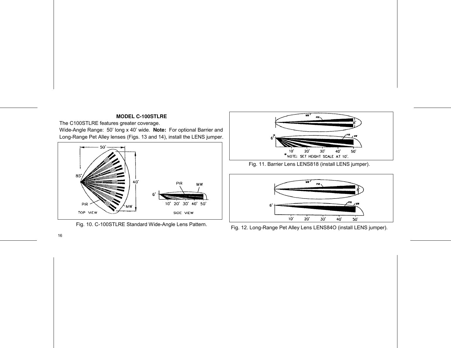
- Coverage (standard wide-angle lens, indoors, 68°F): C-100STE 30'x35'; C-100STLRE 40'x50'
- Operating temperature: -10° to +50°C (14° to 122°F)
- Mounting: Wall or corner, 6' to 10' max height
- Output relay: Form A, Normally-Closed, ~4 second relay time; contacts rated 100mA @ 24VDC
- Status input: panel disarmed >5V, armed <1.5V
- Self-test interval: 11-16 hours (also runs at power-up)
- Power: 12VDC filtered, requires battery backup source. Current draw: idle 33mA, alarm 35mA
- Microwave frequency: X Band
- Dimensions: 4.5" x 2.5" x 1.7" (HxWxD); shipping weight 7 oz.
Ordering Information
- C-100STE — Dual Technology Microwave/PIR Detector
- C-100STLRE — Long-Range Dual Technology Detector
- SVLBKT — Swivel Bracket Kit
- LENS100 — Standard Wide-Angle Lens (factory installed)
- LENS817 — Pet-Alley Lens
- LENS818 — Barrier Lens (C-100STLRE)
- LENS840 — Long-Range Pet Alley Lens
Choosing a Location
- Corner mounting is generally recommended for greater coverage. Select a rigid surface relatively free of vibration.
- Position the sensor so an intruder crosses its field of view — not directly toward or away from it.
- Consider area size/shape, PIR lens choice, obstructions, pets, and the intruder's likely path (typically a door or window) when choosing height and aim.
- Unit ships from the factory with Jumper J1 in the Alarm position.
Installation & Wiring
- Open the case with a small screwdriver in the bottom slot, push up slightly, and remove the front cover.
- Route wires through the push-thru wire entry hole (caulk around wires to eliminate drafts and prevent insect entry).
- Power (Terminals 1[+] & 2[-]): Apply 12VDC, sourced from a control panel or supply with rechargeable battery backup.
- Alarm Relay Form A (Terminals 3 & 4): Normally closed, 100mA @ 24VDC. Opens on intrusion detection or power loss.
- Alarm Relay Form C (Terminals 3, 4 & 5) — where equipped: Terminal 4 common, Terminal 3 normally closed, Terminal 5 normally open.
- Status Input (Terminal 5): Connect to the panel's Arm Lug — a low signal tells the sensor the panel is armed.
- Trouble Output (Terminal 6): Open-collector, active-low output signaling a trouble condition; can be wired to an unused zone for local keypad display.
Setting the Height Scale
Loosen the Lock Screw and slide the circuit board up/down to align the embossed index with the pointer representing your mounting height (6-10 ft, standard lens only), then retighten (don't over-tighten).
Jumper Block Modes
- LENS — install spare jumper only when using the Barrier Lens or Long-Range Pet Alley Lens
- LED — disables LED alarm indication
- PIR — Walk-Test Mode, LED indicates PIR trips only
- ALARM — normal operation, LED indicates simultaneous PIR + microwave trips
- MW — Walk-Test Mode, LED indicates microwave trips only
- 4-Pulse Mode (least sensitive, for hostile environments/pet areas): install both PIR and MW jumpers together
The alarm relay only operates with the LED or ALARM jumper installed — always restore one of these positions after testing.
Testing the Coverage Area
- Allow a 1-minute settling time after wiring, then move your hand across the lens to verify sensor response (LED lights with PIR jumper installed when a beam is disturbed; stays lit with MW jumper installed while motion continues).
- Range test: Install the PIR Walk-Test jumper, walk to the maximum desired coverage distance and across the field. Repeat with MW jumper, then with ALARM jumper.
- Width test: Same jumper sequence, walking across the coverage area.
- Environmental disturbance test (PIR only): With all HVAC/heaters running, leave the area — if a false alarm occurs, cover the entire lens with cardboard. If it still alarms, the issue isn't environmental (check for low supply voltage or an intermittent panel connection). If covering the lens stops it, turn off suspect devices one at a time to isolate the source, then reposition/re-aim as needed.
Zone Masking
If environmental interference can't be resolved by repositioning, apply the supplied zone-masking foil to the grooved inside surface of the offending lens segment to deactivate just that zone. Press the foil down firmly (e.g. with a pen tip) for good contact — oil or grease on the lens/foil reduces adhesion.
Optional Lenses
- Pet Alley Lens (LENS817): Creates an insensitive zone above floor level to ignore pets/pests.
- Barrier Lens (LENS818): Creates an invisible "fence" dividing coverage into two sections — crossing it triggers an alarm. Requires the LENS jumper.
- Long-Range Pet Alley (LENS840, C-100STLRE only): Same pet-immune concept at extended range. Requires the LENS jumper.
Troubleshooting
| Symptom | Probable Cause | Remedy |
|---|---|---|
| Rapid LED flash | Circuitry or microprocessor memory malfunction | Power down 5 sec, power up and wait 1.5 min. If it persists, return for repair. |
| Unit holding loop in alarm | Walk-Test Mode selected | Place jumper in Alarm or LED Disable position. |
Warranty
NAPCO warrants this product free from manufacturing defects for 36 months from the date of manufacture, repairing or replacing at its option. Excludes equipment repaired by others, improperly installed/used/altered, or damaged by acts of God. NAPCO recommends the entire security system be tested weekly.