
Makita Automatic Drapery Opener (ZZCM101/ZZCM301) — Instruction Manual
Full instruction manual for the Makita Automatic Drapery Opener, Models ZZCM101 and ZZCM301.
Full text manual (for reference)
Full instruction manual for the Makita Automatic Drapery Opener, Models ZZCM101 (CM101, with receiving unit) and ZZCM301 (CM301, without receiving unit) — covers assembly, mounting, motor attachment, remote control, timer programming, and troubleshooting.
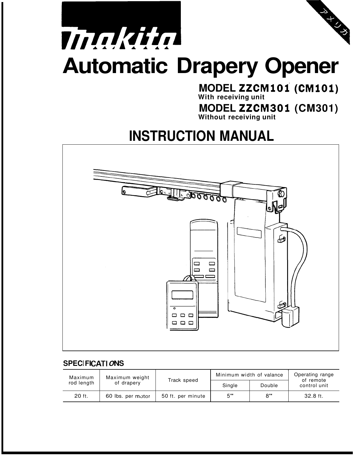
Specifications
- Maximum rod length: 20 ft
- Maximum weight of drapery: 60 lbs per motor
- Track speed: 50 ft per minute
- Minimum width of valance: 5" (single), 8" (double)
- Operating range of remote control unit: 32.8 ft
WARNING — Polarized Plugs: To reduce the risk of electric shock, the motor has a polarized plug (one blade wider than the other) that fits a polarized outlet only one way. If it doesn't fit, reverse the plug; if it still doesn't fit, have a qualified electrician install the proper outlet. Do not modify the plug.
Rod & Motor Assembly Options
- 1 Rod, 1 Motor (9 FT): Motor ZZCM101 (CM101), Remote controller ZZRC10 (RC10), Timer ZZCT10 (CT10). Includes 9ft track, rod assembly with 32 carriers, mounting brackets, white end caps.
- 1 Rod, 1 Motor (18 FT): Uses ZZEC101 (EC101) kit containing components above, plus two 9ft tracks and a splice.
- 2 Rods, 2 Motors (9 FT each): Motors ZZCM101 (CM101) + ZZCM301 (CM301), Remote ZZRC20 (RC20), Timer ZZCT10 (CT10). Two sets of tracks, rod assemblies, brackets, and end caps.
- 2 Rods, 2 Motors (18 FT each): Uses ZZEC201 (EC201) kit with doubled components.
Cutting Track to Size
Length of aluminum track = overall length less 5-1/4" (offsets for the end and motor pulley housings). A hack saw can be used; make 90-degree cuts and remove burrs, especially for one-way applications.
Splicing Tracks
- Center opening: for applications over 9', splice two equal-length tracks together using the supplied splice, centered in the rod.
- One-way: cut only one track to adjust length; place the splice furthest from the motor end. Insert tracks equally into the splice, butting them together.
Rod Assembly — Center Opening Applications
- Remove twist ties from the cable and carefully uncoil to prevent tangles.
- Loosen screws and remove securing plates from each end of the temporary track.
- Detach end and motor pulley housings from the temporary track, then remove closing plates and discard the temporary track.
- Stretch the end and motor pulley housings to the fullest distance the cable allows, making sure the cable is not tangled.
- At the motor pulley housing end, lay the cable into the aluminum track about 4", keeping it untwisted and on the outside of the wheels; insert the closing plate while applying gentle tension. Repeat at the other end. Reinstall securing plates.
- Check the cable rides in the pulley groove in both housings.
- Loosen (do not remove) the cable retaining screw on the closing plate with the overlap arm.
- With pliers, grab the cable sleeve and pull out excess cable while keeping tension, then re-tighten the screw. If movement isn't smooth, check for a twisted cable, improper routing, or misalignment in the pulley groove.
- Adjust center-position of draperies by loosening the retaining screw on the closing plate without the overlap arm, allowing it to slide to the desired center position.
- Remove and discard the temporary steel spacer from the motor pulley housing.
- Using the provided wrench, turn the tension-adjusting bolt clockwise, leaving a gap between tension plates of about 1/16" (thickness of a nickel). Rods over 10' may need more tension to prevent cable slipping.
- Move the cable sleeve up to the closing plate, crimp with pliers, and cut off excess cable.
- The rod assembly ships with the motor on the right side; it can be moved to the left by removing two screws, reversing the arm, and reattaching to the same closing plate (the overlap arm should face into the room).
Rod Assembly — One-Way Operations
Follow steps 1-5 of the center-opening procedure, then remove the screw from the closing plate without the overlap arm (discard that plate). Insert the remaining closing plate (with overlap arm) into the track with tension, attach motor/end pulley housings, and tighten the retaining screw after pulling excess cable taut, following the same tensioning steps (steel spacer removal, tension bolt to 1/16" gap, crimp sleeve). The motor is designed to hide behind the drapery stack — determine right or left stacking; the rod ships set up for right stacking (reverse the overlap arm for left stacking).
Mounting the Rod
- Wall or ceiling mount brackets are supplied; fasteners are not included (choose based on your wall/ceiling material).
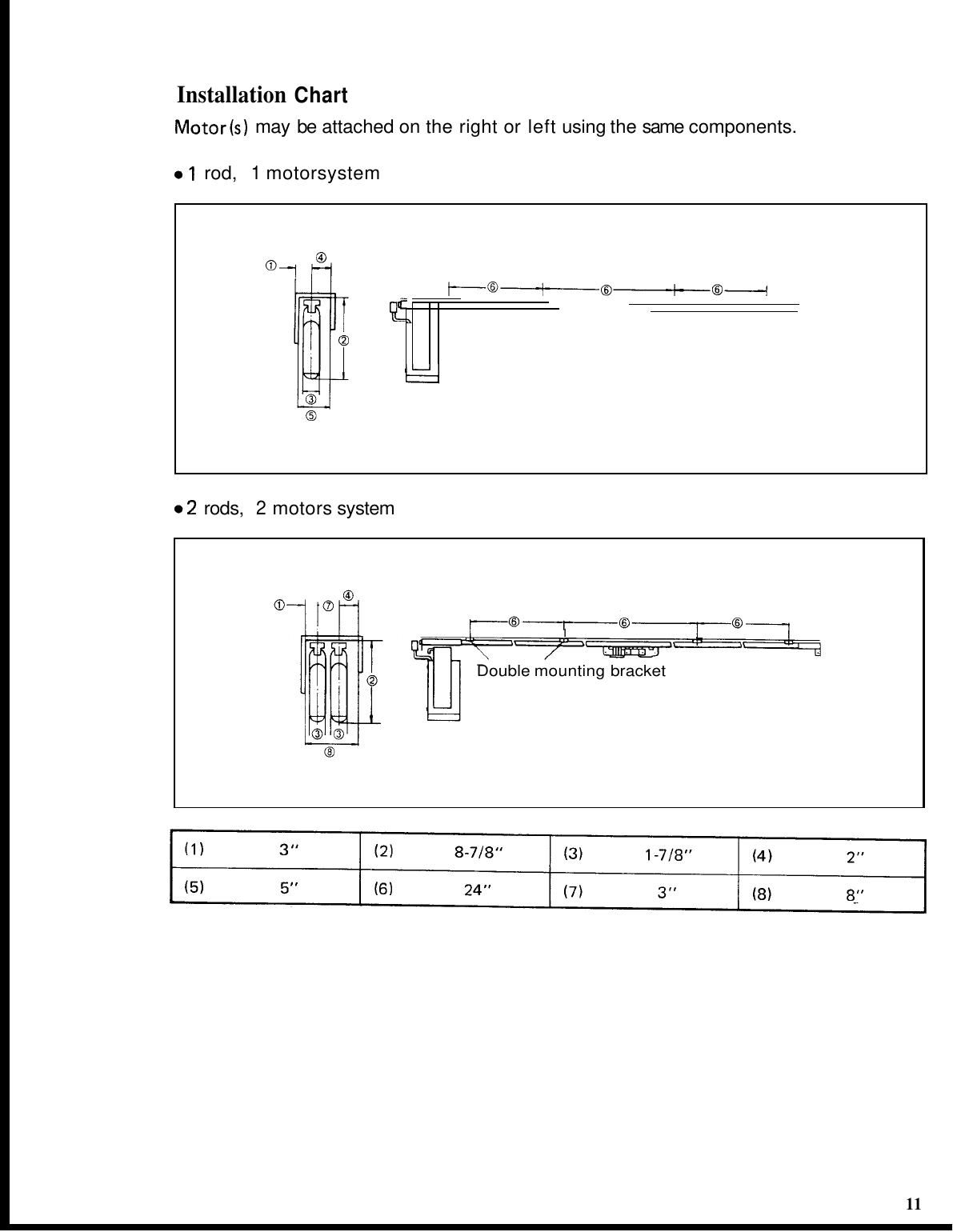
- Attach brackets to the rod approximately every 24", with a bracket close to each end.
- Allow extra space (typically 1-1/2" to 2" greater than drapery length) for floor/track clearance.
- Position the rod, mark bracket mounting holes, then detach brackets, drill, and attach.
- Wall mount brackets can flex to accommodate uneven walls — loosen the ceiling clip screw after installing the rod to let it relax straight, then retighten. For ceiling mounts, shims may be needed.
- Starting at the center of the rod, snap the rod into the brackets until you feel/hear a click.
Loading Carriers
After installing the rod, remove securing plates and load carriers into both ends of the rod (for one-way applications, load from the motor pulley housing end only). Keep the cable on the outside of the wheels while loading. Reinstall securing plates.
Stop (Optional)
The stop gives more pinning position options for attaching draperies. Tighten the securing plate at the end pulley only; leave the motor pulley securing plate loose until the motor is attached, then slide it back over the rubber section and tighten.
Attaching the Motor
One Motor, One Track System
- Hold the motor at a 45° angle to the track, push the lever, insert the shaft into the motor gear hole, and turn the motor parallel to the track. Release the lever to lock it in; gently twist to confirm it's securely attached (some play is normal).
- Slide back the under cover to expose the modular connecting ports.
- Connect the timer to the port labeled "Timer" (attach with the supplied Velcro, ideally hidden behind the drapery stack).
- Return the under cover to its original position.
- Position the infrared receiving eye facing the room, unobstructed (some black-out draperies may require it to be exposed).
- Hang draperies, adjusting pins so the top rides just below the rod.
- Plug the motor into a standard 120V polarized receptacle.
Two Motors, Two Tracks System
- Follow step 1 above starting with the rod closest to the window. With two motors (over/under draperies), the "parent" motor (ZZCM101) goes on the innermost rod (room side); the "kid" motor (ZZCM301) goes on the rod closest to the window.
- Slide back the under cover on both motors.
- Connect the provided modular wire from port "2" on the parent motor to the kid motor, routing it through the retention clips.
- Connect the timer to the "Timer" port on the parent motor.
- Reinstall under covers on both motors.
- Position the infrared receiving eye facing the room, unobstructed.
- Hang draperies.
- Plug both motors into standard 120V polarized receptacles.
Remote Control Unit
Point the remote in the direction of the receiving unit; operating range is 32.8 ft. Buttons: Open (opens drapery), Close (closes drapery), Stop (stops in any position — one push is sufficient; the motor auto-stops at fully open/closed, so no Stop press is needed there). Pressing the same-direction button again while already fully open/closed will not operate. With the two-motor system (ZZCM101 + ZZCM301), No.1 and No.2 buttons on the remote control ZZCM101 and ZZCM301 respectively.
24-Hour Timer — 4 Memory Functions
Controls: TIME (set button), ON/OFF (timer on/off), Open/Close button, Memory Clear button, Memory Display button, Minute Set button, Hour Set button.
CAUTION: Do not install where temperatures exceed 50°C (122°F) or in direct sunlight (can damage the LCD). Avoid excessively low temperatures (may slow LCD response, though this is not permanent). Do not drop, impact, or disassemble the timer.
Installing the Timer
Connect the timer cord to the "TIMER" jack on motor No. 1 (with receiving unit). Attach the timer to a location using the provided Velcro tape.
Setting the Present Time
The display flickers when power is applied. Push the TIME button — Hour, Minute, and AM/PM light steadily (reverts to flickering after ~15 seconds if untouched). Adjust with the H and M buttons (holding advances continuously). About 15 seconds after setting, the display returns automatically to Present Time mode. To sync to the second, push and release the button exactly when the minute changes.
Setting Open/Close Times
Push the memory-select button to enter Timer Set mode (flickers for memory No. 1). Toggle the open/close indicator with the open/close button, then set the time with the H/M buttons. Push the memory-select button again to advance to memories No. 2, 3, and 4. To erase a memory, flicker the desired number then push the erase button.
Timer Function & Confirming Times
Push ON/OFF to actuate the timer (open/close indicator appears); push again to turn it off. Push MEMO to cycle through and confirm the set times for memories 1-4. Opening/closing operation takes about 6 seconds, during which remote control operation is not possible. If the motor is unplugged or power fails, all memory and the present time are lost and must be reprogrammed.
Maintenance: Wipe the timer with a soft, dry cloth — do not use alcohol, benzene, or thinner-type products.
Optional Accessories — Wall Switch
For Class 2 wiring only; usable in conjunction with ZZCM101 (CM101). Model ZZWS10 (WS10) for one motor, Model ZZWS20 (WS20) for two motors.
Installation Chart — Mounting Configurations
Maintenance & Troubleshooting
After assembly, connect to power and test manual and automatic operation.
| Problem | Cause | Solution |
|---|---|---|
| Remote control does not operate | Power plug not engaged properly; battery dead; receiving unit obstructed | Plug in properly; replace remote battery; remove obstruction |
| Motor does not stop automatically at fully open/closed | Not enough cable tension | Increase tension via the tension-adjusting hex bolt |
| Can operate ZZCM101 but not ZZCM301 | Modular cord between motors not connected properly | Reconnect per manual instructions |
| Drapery stops automatically without pushing a button | Interference with drapery movement | Remove the obstructing object |
| Cannot open/close drapery by hand | Incorrect track assembly | Re-assemble the track per manual instructions |
Repairs should be performed by Makita Authorized or Factory Service Centers using Makita replacement parts.
Warranty
Makita Limited Three Year Warranty: every motor is inspected and tested before leaving the factory, warranted free of defects in workmanship and materials for three years from the date of original purchase. Return the complete motor, freight prepaid, to a Makita Factory or Authorized Service Center. Does not apply where repairs have been attempted by others, normal wear and tear, abuse/misuse/improper maintenance, or alterations.