
Lorex LH310 Series Edge DVR (4/8/16-Channel) — Instruction Manual
Instruction manual for the Lorex LH310 Series Edge DVR, covering setup, recording, playback, remote viewing (DVR Netviewer), and troubleshooting.
Full text manual (for reference)
Instruction manual for the Lorex LH310 Series Edge DVR (4/8/16-channel) — a BNC-camera digital video recorder with remote viewing via DVR Netviewer, motion/alarm event recording, and USB backup.
Overview
The system comes with the Edge DVR, power supply, remote control, USB mouse, DVI/VGA adapter (8/16-channel only), Flex-IR extender, mounting kit, Ethernet cable, and printed documentation. It's designed to mount directly to the back of most VESA-mount LCD monitors, or sit in a standard horizontal position / wall mount.
Basic Setup
- Mount the system: Screw the mounting screws into the two top holes on the back of your LCD monitor (leave 3/4 of the way in for clearance), then hang the DVR (front panel facing up) onto the screws.
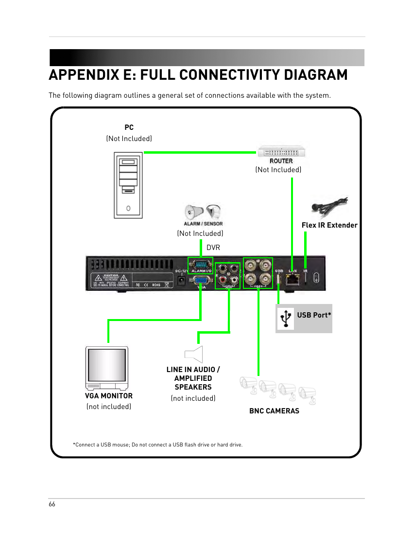
- Connect the cameras: Connect BNC cameras to the BNC ports on the rear panel.
- Connect the monitor: Use the VGA port (4CH) or DVI port (8/16CH) to connect your monitor (cable not included).
- Connect the Ethernet cable: Connect the included Ethernet cable from the LAN port to an empty port on your router.
- Connect the Flex-IR Extender: Plug it into the rear IR port and position it near the front of the monitor for clear remote-control signal line-of-sight (not required for normal operation).
Front & Rear Panel
- Front panel (all models): IR receiver, USB port (front panel only — for backup/firmware, not the rear USB port), power LED, HDD activity LED.
- Rear panel (4-channel): Exhaust slots, DC 12V power in, Alarm I/O (D-sub 9), Audio In, 4x BNC Video In, USB (for mouse), LAN (RJ-45), VGA out, Audio Out (2 channels), IR port.
- Rear panel (8/16-channel): 8 or 16x BNC Video In, Audio In, Alarm I/O, Audio Out, DVI out, LAN, IR, USB (mouse), DC 12V in, ground.
Mouse & Remote Control
The mouse is the primary input device: left-click to select menu options or (in split-screen) view a channel full-screen; right-click to go back/exit menus; scroll wheel to change values or set playback markers. Connect the mouse to the rear USB port only — the front USB port is reserved for backup/firmware drives.
The remote control (battery: CR2025) provides secondary navigation: MENU opens the main menu, LIST opens the Event List, OSD toggles the on-screen display, directional buttons navigate menus/channels, and dedicated buttons control playback speed, screenshots, and split-screen views.
Starting the System & On-Screen Display
On power-up the system runs a basic check and boots into Live Mode. The status bar shows recording mode, language, and HDD/USB device status; the display area shows single-channel or split-screen views (disconnected cameras show a blue "VLOSS" screen); the toolbar provides one-click access to channel views, Main Menu, playback controls, Event List, and OSD toggle.
Split-Screen Selector (8/16-channel only): Choose quad, 9-split, or 16-split (16-channel only) grid layouts for live viewing and playback.
Setting the Date and Time
Open the Main Menu → Setup → Date/Time Setup. Choose the date format (Y/M/D, D/M/Y, or M/Y/D) and set date/time with the scroll wheel, then click Exit/Update to save.
Recording
By default the system immediately records continuously from all connected cameras. You can configure it to stop when the drive is full, or overwrite the oldest data continuously. Three event-recording modes are available:
- Motion: Records when motion is detected on the affected camera.
- Alarm: Records when an alarm/sensor is triggered.
- Video Loss: Records when a camera disconnects, with pre-record capturing video from seconds before the loss.
Two audio channels can be recorded if audio-enabled cameras are connected (audio is only available on channels 1 and 2).
Playback & Event List
From Live View, click the playback icon to enter Playback Mode; select date/time/frame and confirm. Controls include pause/resume, reverse/forward speed (5x/15x/60x), Split-Screen Selector, and Event List access. Click anywhere in the playback bar to drop an orange marker for faster future searching; Smart Search populates additional colored markers automatically.
The Event List (max. 4,096 saved events) can be filtered by channel and by Smart Search category: All, Motion, Video Loss, Alarm, HDD ON/OFF, Power ON/OFF, Mark, or USB. Selecting an event and clicking play jumps straight to that point in Playback Mode.
Managing Passwords
| User ID | Role | Default Password | Permissions |
|---|---|---|---|
| ID 1 | Normal user | 1111 | Full control except changing passwords or password checking |
| ID 2 | Administrator | 2222 | Full control, can change all passwords and enable/disable password checking |
Enter passwords via the on-screen graphical Password Wheel (click digits 0–9 with the mouse). Change passwords from Main Menu → Setup → DVR Password (admin login required).
Main Menu Reference
- Camera: Adjust Brightness, Contrast, Hue, and Saturation per camera.
- Setup: Date/Time, system language (18 languages supported), NTSC/PAL/Auto video format, fan speed (8/16CH), DVR password, and system information (software/hardware/disk/LAN).
- Record: Alarm/Motion Rate, Working/Non-working Hour Rate (0–15 fps per camera), image quality (1–5), audio enable (channels 1–2 only), resolution (640x240 or 640x480), Record Mode (Single-Way / Overwrite / No Record), weekly recording Schedule grid, and Format HDD.
- Alarm: Video Loss Alarm and Motion Enable per camera, VLoss Response Time (0–180s or Infinite), Response Duration (1–255s), Alarm Full Screen, Buzzer, Alarm-In/Alarm-Out setup (8/16CH), Alarm/Motion Schedule, and per-camera Motion detection grids with adjustable sensitivity (0–100).
- Backup: Format a USB flash drive (128MB–8GB supported), then set Start/Stop time and channel to export MOV backup files (front-panel USB port only).
- LAN: Configure IP, Mask, Gateway, DHCP (8/16CH), HTTP Port, and QuickTime HTTP Port (4CH); manage LAN passwords for remote viewer access (Guest/User/Administrator).
Storage note: Formatting the HDD or a USB drive erases all data and cannot be undone. Only the front-panel USB port supports backup/firmware transfer — the rear USB port is for the mouse only.
Backup File Naming
ch_##YYYYMMDDhhmmss.mov — channel number, year, month, day, hour, minute, second. Backup files play via the Event List on the DVR itself, or on a PC using QuickTime Player.
Remote Access: DVR Netviewer
DVR Netviewer is the built-in browser-based remote surveillance client, accessible from any PC with Internet Explorer 6+ (Firefox supported via the IE Tab plug-in). Requirements: Pentium 4+ CPU, Windows XP/Vista, 128MB RAM, 16MB video memory, 10/100 BaseT LAN, 384 Kbps+ upstream WAN, and Windows Media Player 10+ (8/16CH) or QuickTime Player 7+ (4CH).
4-channel models require QuickTime configuration first (Edit → Preferences → Advanced → Transport Setup: Custom → Transport Protocol: HTTP → Port 80, or your custom port). 8/16-channel models require installing the ActiveX plug-in on first login.
Network user profiles (separate from local DVR passwords):
- Administrator — ID 9, default password 3333 — live viewing, playback, network config permissions
- User — ID 8, default password 2222 — live viewing and playback
- Guest — ID 7, default password 1111 — live viewing only
For security, change the default HTTP port 80 to a port not blocked by your ISP (see the port-forwarding appendix). The default DVR IP address is 192.168.1.89.
Appendix A: System Specifications
| Spec | Value |
|---|---|
| Hard disk capacity | 1x HDD, up to 1TB, 100% duty cycle |
| Operating system | Linux (embedded) |
| Backup | USB flash drive, front panel port only; MOV format; H.264 compression |
| Recording resolution | NTSC: 640x240, 640x480; PAL: 640x256, 640x512 |
| Recording speed | 4CH: 60fps NTSC/50fps PAL @640x240/256; 8/16CH: 120fps NTSC/100fps PAL |
| Event/log search | Up to 4,096 events (alarm, motion, video loss, power loss) |
| Video inputs | 4/8/16 x 1Vp-p, 0.75 ohms, BNC (by model) |
| Video outputs | 1x VGA (4CH) or 1x DVI (8/16CH) |
| Audio I/O | 2x line-in RCA, 2x line-out RCA |
| Alarm I/O | 4x TTL in (8/16CH programmable NC/NO); 1x relay out (NO/NC) |
| Network | 10/100 Mbps Base-TX RJ-45; TCP/IP, DDNS, Web protocols |
| Supply voltage | 120-240 VAC input; 12V DC, 2.5A (4CH) or 3A (8/16CH), 50/60Hz |
| Power consumption | ~30 watts |
| Operating temperature | 41°–104°F (5°–40°C) |
| Unit weight / dimensions | 3.19 lbs (1.45 kg); 11.4" x 1.6" x 7.0" (290 x 42 x 180mm) |
Replacing / Formatting the Hard Drive
Connect the power and data cables to the replacement SATA hard drive (each connects only one way), place it in the housing (insert toward the front panel, lower, slide toward the rear), then re-secure all mounting screws and panels. After powering on, a newly installed drive must be formatted (Main Menu → Record → Format HDD → Yes) — this erases all data and cannot be undone.
Connecting Audio
Connect RCA audio cables from audio-capable cameras to the Audio In 1/2 ports, and RCA cables from Audio Out to line/amplified speakers (the two audio-out ports are separate mono channels, not stereo L/R). Enable audio per-camera from Main Menu → Alarm/Audio settings (channels 1–2 only).
Taking Screenshots (8/16-channel only)
Connect and format a USB flash drive in the front panel, select the display view to capture, then click the screenshot icon. Files save as JPEGs named KMMDD00x.jpg in the Picture folder on the USB drive.
Troubleshooting
| Issue | Cause & Fix |
|---|---|
| System not powering up | Confirm all cables connected; bypass power bars/surge protectors; test the outlet with another device. |
| Remote control not detected | Install a fresh CR2025 battery. |
| Hard drive not detected | Open the housing and check that hard drive cables are firmly connected, or install a 3.5" SATA drive if missing. |
| Hard drive full (0%), no longer recording | Enable Overwrite mode: Main Menu → Record → Record Mode. |
| Mouse not detected | Firmly connect the mouse to the rear USB port; power-cycle the system if needed. |
| No picture on selected channel | Check/reseat the camera video cable; try another channel or cable to isolate the fault. |
| Picture but no sound | Check the Audio In/Out cable connections and confirm audio is enabled in the camera configuration. |
Warranty & Notice
As products are subject to continuous improvement, Lorex Technology Inc. and its subsidiaries reserve the right to modify product design, specifications, and prices without notice or obligation.