
JascoPro 76598 (ZWN4016) Z-Wave Plus In-Wall Smart Toggle Switch — Installation Manual
Installation manual for the JascoPro Series In-Wall Smart Toggle Switch (Model 76598 / ZWN4016), a Z-Wave Plus LR certified lighting control switch, covering single-pole and 3-way wiring.
Full text manual (for reference)
Quick reference guide for the Jasco Pro Series In-Wall Smart Toggle Switch (Model 76598 / ZWN4016), a Z-Wave Plus LR certified in-wall lighting control switch. This manual is presented as bilingual/trilingual wiring diagrams rather than running text; the images below reproduce the full installation diagrams. The full downloadable PDF includes Spanish and French versions of the same content.
⚠ Warning — Shock Hazard
Turn OFF power to the branch circuit for the device being replaced before removing the switch. Verify power is off using a non-contact voltage tester. Failure to do so may result in electric shock or death.
Specifications
| Certifications | UL 20B, UL 1310, FCC Part 15, CSA, C-UL |
| Compliance | RoHS |
| Radio frequency | 908.42 MHz (Z-Wave Plus LR) |
| Range | Up to 130 ft (39.62m) line-of-sight between devices |
| Nominal voltage | 120VAC 60Hz |
| Total load | 600W Incandescent, 300W LED/CFL, ½ HP Motor Load |
| Operating temp | 32°F to 104°F (0°C to 40°C) |
| Wire gauge | #12-14 AWG (2.5-4mm²) |
Important: the fixture controlled by this switch must not exceed switch ratings. Designed only for use with permanently-installed fixtures.
Adding the Device to a Z-Wave Network
- Follow the instructions for your Z-Wave certified controller to add a device to your network.
- Bring the controller close to the switch, or press and hold the top or bottom of the paddle for 3 seconds; the controller may need to complete a network scan.
- Note: the manual method should only be used if your network's pairing controller is missing or inoperable.
- SmartStart: scan the QR code on the product with a controller that supports SmartStart inclusion — no further action needed, the device joins automatically within 10 minutes of power-on.
Basic Operation
- Extend paddle (top): turns light ON
- Retract paddle (bottom): turns light OFF
- Air gap switch (accessed via top of paddle): fully disconnects power for safe servicing
- LED indicator: shows on/off and network status
Single-Switch Wiring
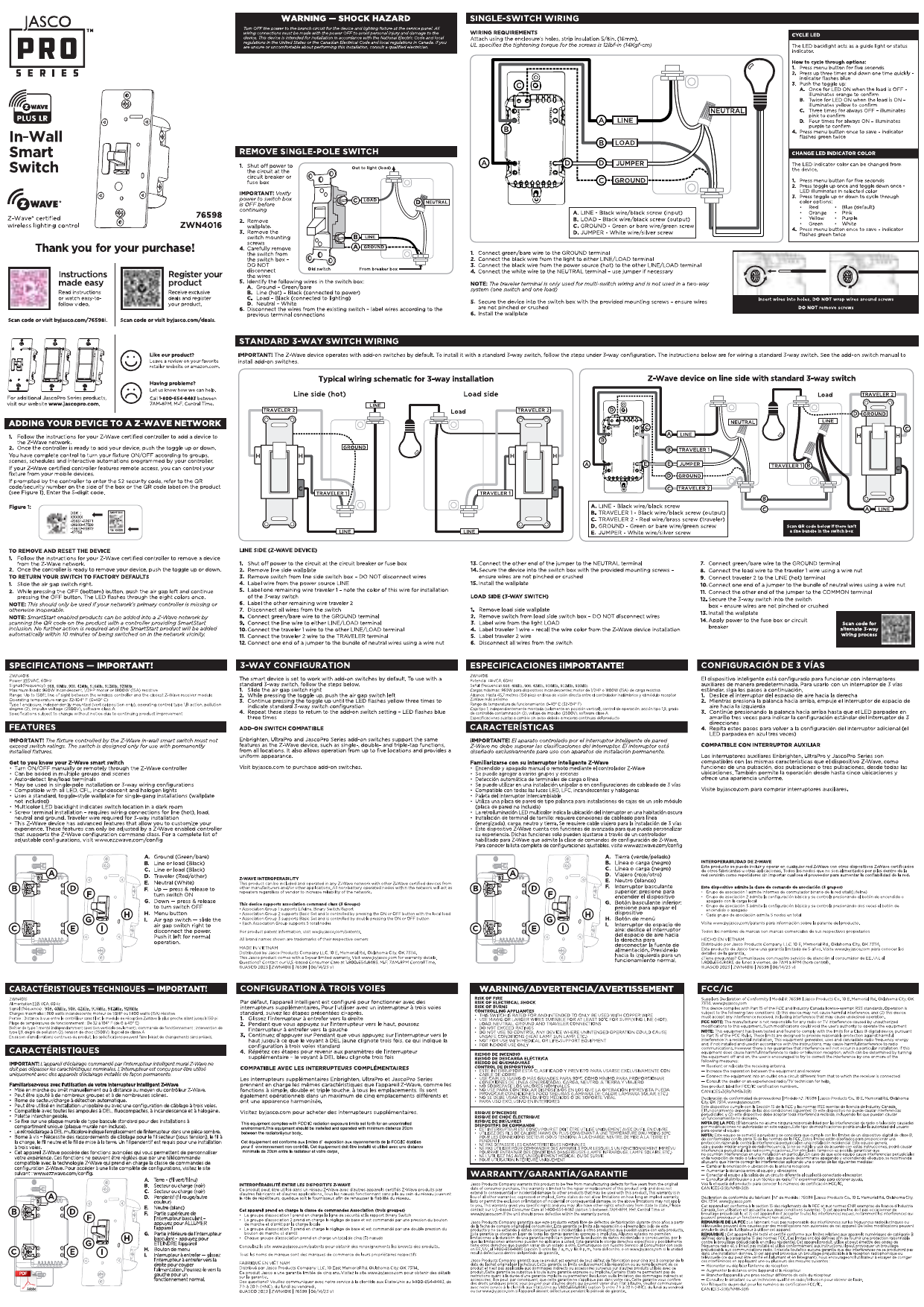
Terminal connections for a standard single-pole installation:
- LINE — black wire / black screw (power source side)
- LOAD — black wire / black screw (fixture side)
- GROUND — green or bare wire / green screw
- NEUTRAL — white wire
Screw torque spec: 12 kgf-in (14 kgf-cm) per UL requirements. Strip wire insulation to 0.9m (36mm, transcription note: check PDF for exact figure — likely 3/8"/9.5mm) before connecting.
Removing an Existing Single-Pole Switch
- Verify power to the switch box is OFF before removing the switch.
- Remove the wallplate, then carefully remove the switch from the wall mounting box.
- Identify: Line (Hot, black, connected to power), Load (black, connected to lighting), Neutral (white).
- Disconnect wires from the existing switch and label them by their previous terminal position.
Standard 3-Way Switch Wiring
The Jasco Z-Wave device works with a standard companion 3-way switch. It can be installed on either the line side or the load side of the 3-way circuit.
Z-Wave Device on Line Side (with standard 3-way switch on load side)
- Shut off power to the circuit at the breaker or fuse box.
- Remove the wallplate and switch from the wall box; label all wires by their existing terminal connections.
- Connect the ground wire (green/bare) to the GROUND terminal.
- Connect LINE, LOAD, TRAVELER 1, and TRAVELER 2 per the terminal diagram (see image below).
Terminal legend: A. LINE (black/black screw) · B. LOAD (black/black screw) · C. TRAVELER 1 (black/black screw) · D. TRAVELER 2 (black/black screw) · E. GROUND (green or bare/green screw)
3-Way Configuration (Pairing the Switches)
The smart device is set to work with either switch by default. To pair with a standard 3-way companion switch:
- Move the paddle to the up position.
- While pressing the top of the paddle, hold and press the ON/OFF button.
- Continue pressing the bottom of the paddle to confirm the lighting connection.
- Repeat for a second companion switch, if applicable.
Visit bylasco.com to purchase compatible add-on switches for 3-way and multi-way installations.
Factory Reset
- Flip the air gap switch (at the top of the paddle) to cut power.
- While pressing and holding the OFF (bottom) button, push the air gap back in and continue holding OFF until the LED flashes through a bright green LED sequence.
- Once the sequence completes, the switch returns to factory default.
Removal from a Z-Wave Network
- Follow your Z-Wave controller's instructions to put it into "remove device" mode.
- Once ready, toggle the paddle up or down to complete removal.
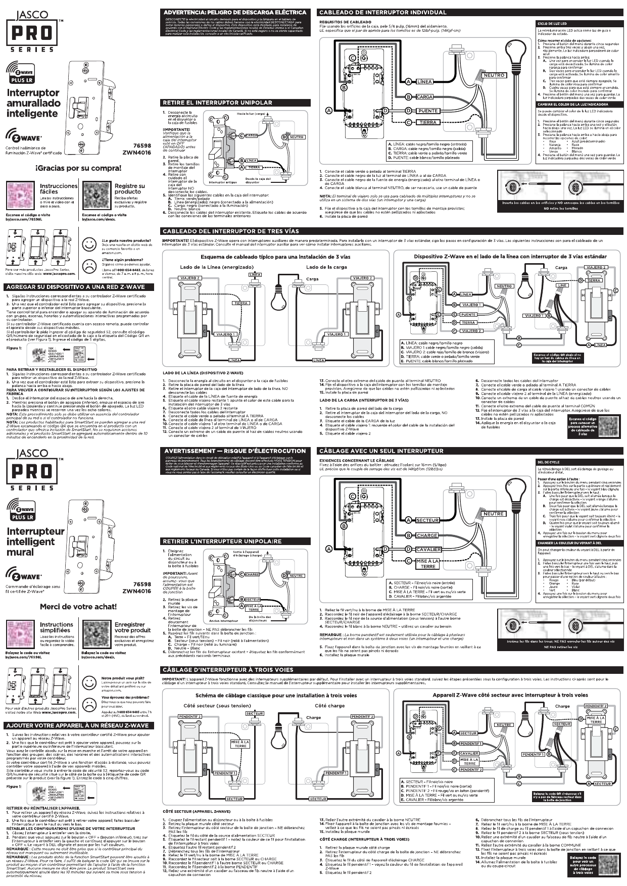
Reference Diagrams
Support
Jasco — 1-800-654-8483 (option 3) | bylasco.com/support | Product page: bylasco.com/76598 | Reset video: bylasco.com/reset