
ION Digital Plunger Wireless Door Security Sensor — Installation Instructions
Complete installation instructions for the ION Plunger recessed transmitter — a concealed wireless door security sensor with a captive magnet, installed flush inside the door frame.
Full text manual (for reference)
Installation instructions for the ION PLUNGER™ Recessed Transmitter by ION Digital — a concealed reed-switch magnet contact for door protection, powered by a long-life replaceable lithium battery, that mounts flush inside a drilled hole in the door frame.
General Information
The ION Plunger recessed transmitter is a reed switch magnet contact that provides concealed protection for doors. It is powered by a long-life lithium battery that is easily replaceable when a low-battery condition is indicated by the control. The electronics in the MICRA and the PLUNGER are identical; however, in the PLUNGER the magnet is captive in the plastic housing and doesn't require a separate magnet on the door itself — making installation easier and minimizing the required gap between door and frame. The MICRA can be used on doors as well as windows; the PLUNGER is not recommended for windows, since it would require a hole drilled through both the inner and outer skin of the frame, creating the possibility of water ingress and damage.
Programming the ID Number
Each ION Plunger has its own unique identification code (electronic serial number, ESN) permanently assigned during manufacturing, located on the label attached to the antenna — this should never be removed. The control unit (receiver panel) must "enroll" the transmitter's ID during system installation. For receiver panels requiring a "Tamper" signal to enroll the sensor, each Plunger automatically sends a Tamper signal upon startup when the battery is inserted. If the unit doesn't enroll, remove the battery, touch the battery and clips together briefly with a small screwdriver, and reinsert the battery.
Installation Steps
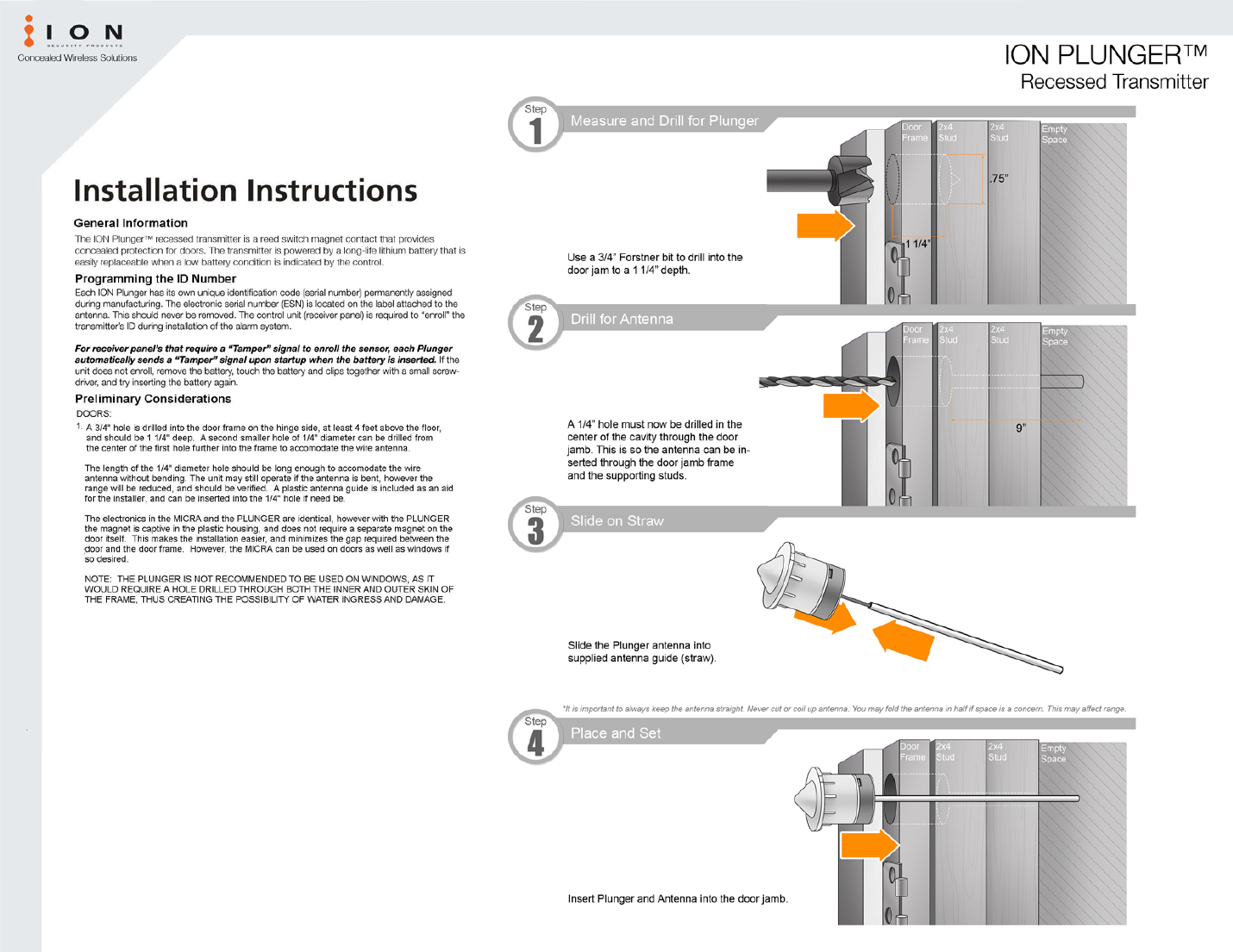
- Measure and Drill for Plunger: Use a 3/4" Forstner bit to drill into the door jamb, at least 4 feet above the floor, to a 1-1/4" depth.
- Drill for Antenna: Drill a 1/4" hole in the center of the cavity through the door jamb (and supporting studs), long enough to accommodate the wire antenna without bending (typically 9" or more).
- Slide on Straw: Slide the Plunger antenna into the supplied antenna guide (straw). Always keep the antenna straight — never cut or coil it. It may be folded in half if space is a concern, though this may reduce range.
- Place and Set: Insert the Plunger and antenna into the door jamb.
Mounting
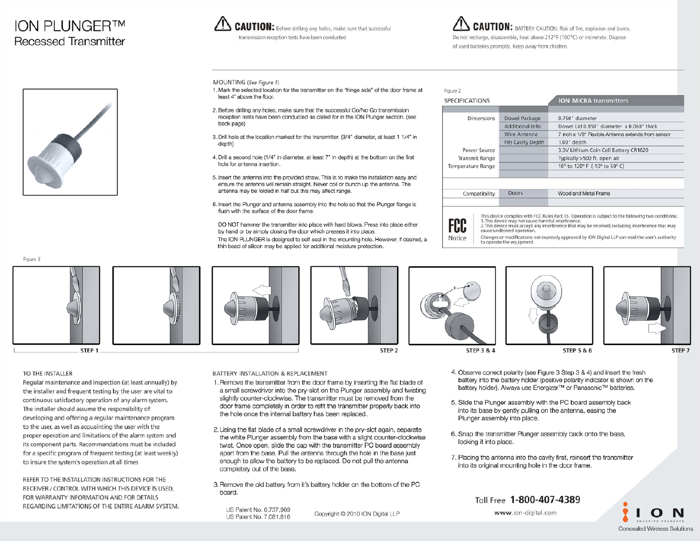
- Mark the selected location on the "hinge side" of the door frame, at least 4 feet above the floor.
- Before drilling, confirm successful Go/No-Go transmission reception tests have been conducted.
- Drill a hole at the marked location (3/4" diameter, at least 1-1/4" depth).
- Drill a second hole (1/4" diameter, at least 7" depth) at the bottom of the first hole for antenna insertion.
- Insert the antenna into the provided straw to keep it straight during installation. Never coil or bunch the antenna — it may be folded in half, but this may affect range.
- Insert the Plunger and antenna assembly into the hole so the flange is flush with the door frame surface.
Do not hammer the transmitter into place with hard blows — press into place by hand or by closing the door, which presses it in. The ION Plunger is designed to self-seal in the mounting hole; a thin bead of silicone may be applied for additional moisture protection if desired.
Battery Installation & Replacement
- Remove the transmitter from the door frame: insert the flat blade of a small screwdriver into the pry-slot on the Plunger assembly and twist slightly counter-clockwise. The transmitter must come out completely to refit properly once the battery is replaced.
- Using the screwdriver in the pry-slot again, separate the white Plunger assembly from the base with a slight counter-clockwise twist. Slide the cap with the PC board assembly apart from the base. Pull the antenna through the hole in the base just enough to replace the battery — do not pull it completely out.
- Remove the old battery from its holder on the bottom of the PC board.
- Observe correct polarity (positive polarity indicator shown on the battery holder) and insert the fresh battery. Always use Energizer™ or Panasonic™ batteries.
- Slide the Plunger assembly with the PC board back into its base by gently pulling on the antenna, easing it into place.
- Snap the transmitter Plunger assembly back onto the base, locking it into place.
- Placing the antenna into the cavity first, reinsert the transmitter into its original mounting hole.
Specifications
| Category | Spec |
|---|---|
| Dowel Package | 0.750" diameter |
| Dowel Lid | 0.850" diameter x 0.060" thick |
| Wire Antenna | 7 inch x 1/8" flexible antenna, extends from sensor |
| Fits Cavity Depth | 1.00" depth |
| Power Source | 3.0V Lithium Coin Cell Battery, CR1620 |
| Transmit Range | Typically >500 ft. open air |
| Temperature Range | 10° to 120°F (-10° to 50°C) |
| Compatibility | Wood and metal frame doors |
Safety Warnings
- Caution: Before drilling any holes, make sure successful transmission reception tests have been conducted.
- Battery Caution: Risk of fire, explosion, and burns. Do not recharge, disassemble, heat above 212°F (100°C), or incinerate. Dispose of used batteries promptly. Keep away from children.
FCC Notice
This device complies with FCC Rules Part 15. Operation is subject to the following two conditions: (1) this device may not cause harmful interference, and (2) this device must accept any interference that may be received, including interference that may cause undesired operation. Changes or modifications not expressly approved by ION Digital LLP can void the user's authority to operate the equipment.
Maintenance
Regular maintenance and inspection (at least annually) by the installer, and frequent testing by the user (at least weekly), are vital to continuous satisfactory operation of any alarm system. Refer to the installation instructions for the receiver/control used with this device for warranty information and details regarding limitations of the entire alarm system.
US Patent No. 6,737,969 · US Patent No. 7,081,816 · Copyright © 2010 ION Digital LLP · Toll Free 1-800-407-4389 · www.ion-digital.com