
Intrasonic I2000 Music & Intercom System — Installation Manual
Installation Manual for the Intrasonic I2000 whole-house Music & Intercom system, covering wiring, roughing-in, RJ45 crimping, and door/gate/amplifier/chime hookup.
Full text manual (for reference)
Installation Manual for the Intrasonic I2000 whole-house Music & Intercom system — covers wiring, roughing-in, RJ45 crimping, door/gate release hookup, external amplifier wiring, and external door chime wiring for the master unit and room, patio, and door stations.
Safety Instructions
- Read all instructions in their entirety before installing the I2000 system.
- To reduce risk of electrical shock, the system must be installed by a qualified installer or dealer.
- Do not attempt to remove or repair the I2000 system — call a qualified installer or dealer.
- Do not expose any part of the system to water.
- Do not install a room, patio, or door station within 10 feet of each other, back to back in the same wall cavity, or on walls facing each other.
- Do not mix the I2000 system with any other system — it is only compatible with other I2000 products.
- Do not use staple cables or wire splices.
- Use a dedicated 110V line to the master unit.
- Do not install near light switches, dimmer controls, air conditioning ducts, metal plates, or heat sources.
- Do not exceed 300 feet for any wire run from the master to a room, patio, or door station.
- Do not daisy-chain any part of the system — all stations must run back to the master.
- Label all wires running back to the master.
- Only one Auxiliary input can be installed per I2000 system.
Wiring
I2000M (Master)
Run a dedicated 110V line from the circuit breaker to where the I2000M master unit will be mounted. Important: not using a dedicated line could cause popping, humming, or buzzing.
I2000R, I2000P, I2000D, I2000VC, AUXWP
Run Cat5 wire from each room, patio, door, volume control, or auxiliary unit location back to the master.
- Maximum of 20 units (room, patio, door, and volume control) in any combination.
- Maximum cable run length is 300 feet per station.
- Only one AUXWP per I2000M unit — locate it wherever you want to use an external source.
- Label all wires by type and location; consider naming/numbering units for clarity (e.g. master bedroom, kitchen, garage).
- Leave sufficient slack at each end of the Cat5 run for future wiring adjustments.
AM/FM Antenna
The FM antenna is the long black wire with a coaxial end that splits into red and black wires; the coaxial end stays at the master unit (with slack), while the red/black wires run to the attic (or the highest point of the house) and split apart as far as possible, nailed to studs for best reception. The AM antenna is the black wire with an antenna mount; the round metal piece connects to the coaxial piece on the master (before the FM antenna is connected), and the two wires clip into the black clips on the back of the master next to the coaxial end. The antenna mount runs up to the attic. Important: to limit interference, keep antenna wires away from other power wires and sources.
External Speaker Wiring
Run 16-gauge speaker wire from the master, room, or patio unit to where the external speaker will be mounted. For two speakers on one unit, wire them in series. Leave a service loop of at least 10 inches of cable at both ends.
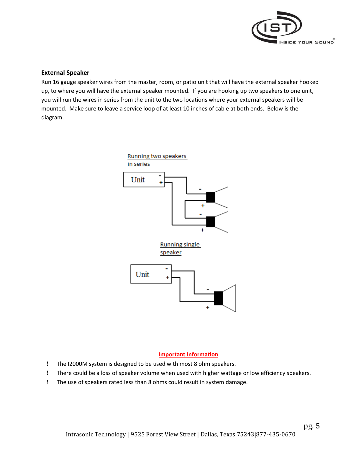
Important: the system is designed for most 8-ohm speakers. Higher-wattage or low-efficiency speakers may lose volume, and speakers rated below 8 ohms could damage the system.
Roughing In
I2000M Master Unit
The I2000M uses the I2000H housing unit, installed between wall studs before drywall goes up. Housing dimensions: 14½" × 5¾" × 3¼". Keep the electrical box on the bottom; typical mounting height is 50 inches off the floor. Screw the housing into the studs, ensuring it is level, then install the electrical outlet box into the master's slot and hook up the dedicated 110V line.
I2000R, I2000P, I2000D (Room, Patio, Door)
These use a standard-depth plastic 2-gang box (suggested: Carlon model B232 or BH235 series), typically mounted 50 inches off the floor. Feed the Cat5 wiring through the box before mounting it in the cut sheet-rock opening. Recess and surface-mount box options are available: IPSMB/IPRSB for patio (I2000P), IDSMB/IDRSB for door (I2000D).
I2000VC, AUXWP (Volume Control, Auxiliary)
These use a standard single-gang box — feed the Cat5 wiring through before mounting.
Crimping RJ45
Follow the color-code diagram (568A standard) and crimp both ends of each cable identically. Test each cable for shorts and opens with an RJ45 tester (not 100% accurate — there's an additional test method once all units are installed; see Troubleshooting).
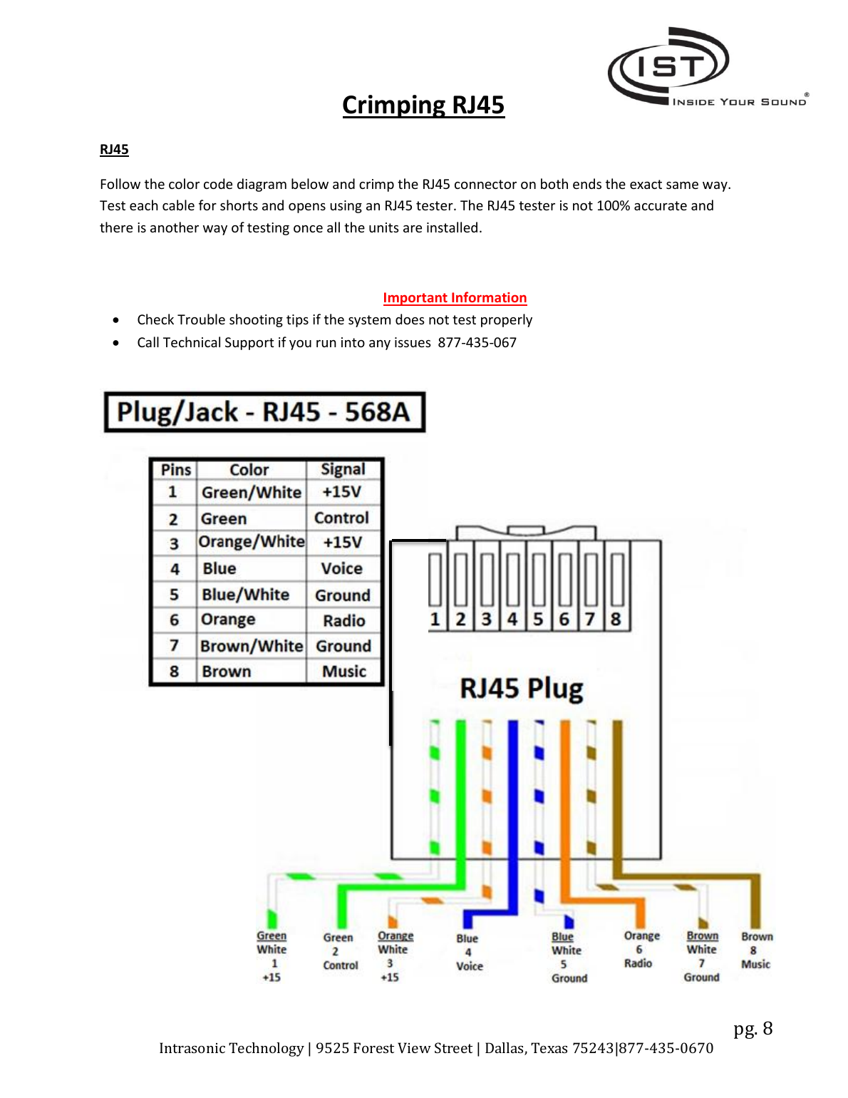
Important: check the Troubleshooting Tips if the system doesn't test properly, or call Technical Support at 877-435-0670.
Door or Gate Release
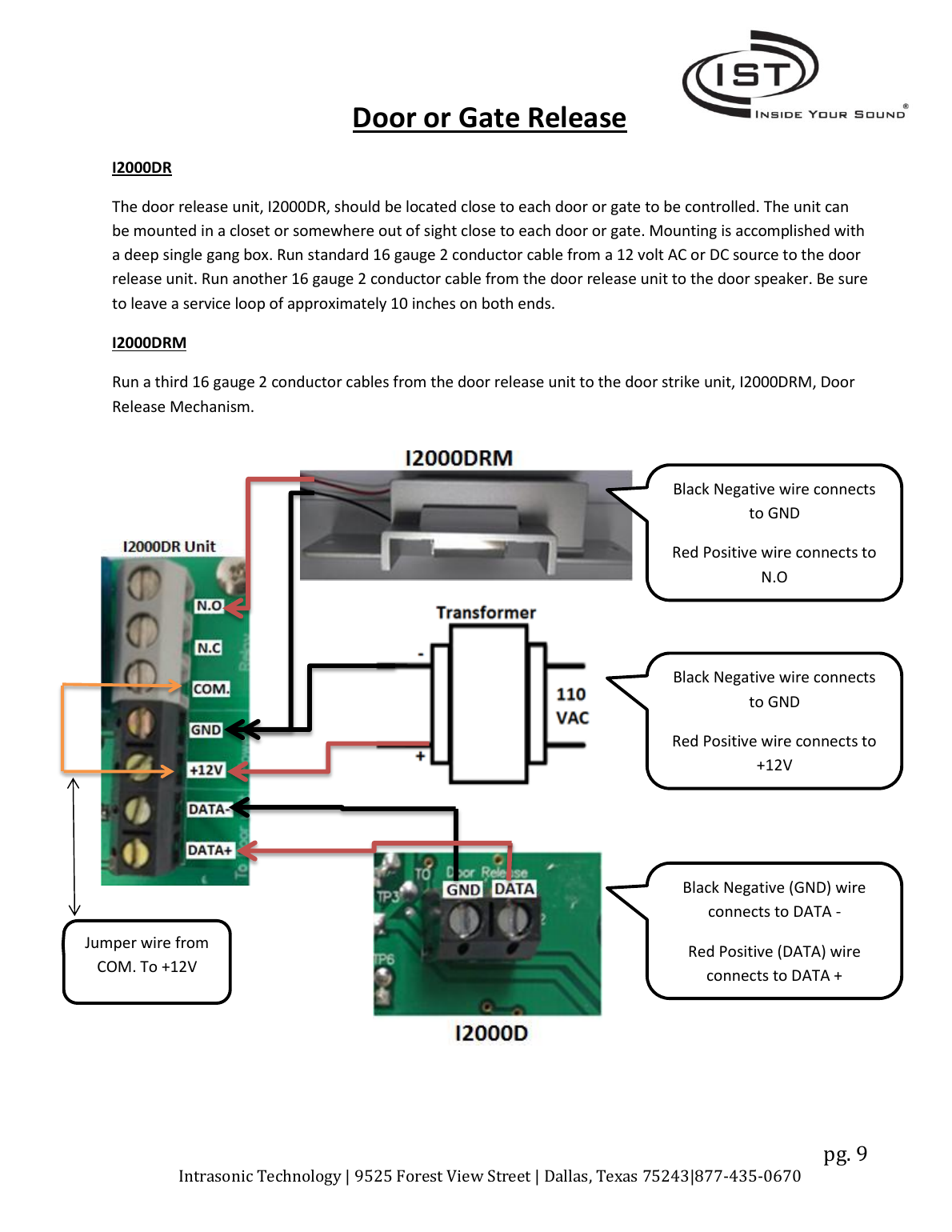
The I2000DR door release unit should be located close to each door or gate — a closet or other out-of-sight spot works. Mount with a deep single-gang box. Run standard 16-gauge 2-conductor cable from a 12V AC or DC source to the door release unit, and another from the door release unit to the door speaker (leave a ~10 inch service loop at both ends). For the I2000DRM Door Release Mechanism, run a third 16-gauge 2-conductor cable from the door release unit to the strike unit.
Wiring for an External Amplifier
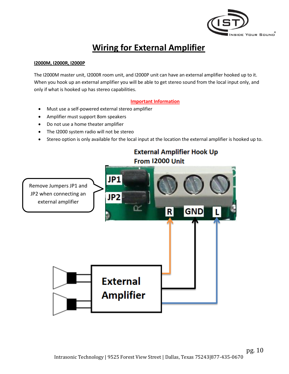
The I2000M, I2000R, and I2000P units can drive an external amplifier for stereo sound — but only from the local input, and only if that input source has stereo capability.
- Must use a self-powered external stereo amplifier.
- Amplifier must support 8-ohm speakers.
- Do not use a home theater amplifier.
- The I2000 system radio itself will not be stereo.
- Stereo is only available for the local input at the location where the external amplifier is connected.
Wiring for an External Door Chime
Requires an AC transformer to power the external chime (24VAC max). This is used with the I2000D door unit.
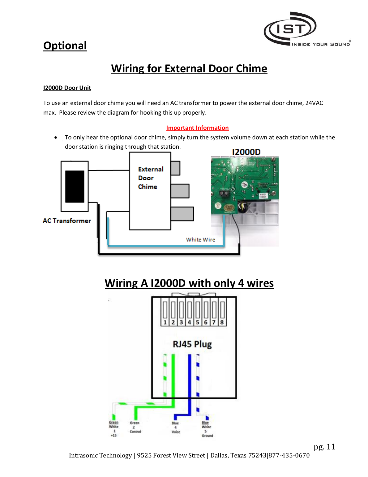
Important: to hear the door chime only at a specific station, simply turn the system volume down at other stations while the door station is ringing through.
Warranty
Intrasonic Technology warrants its products free of manufacturing defects for two years from the date of closing or installation, applicable only to products purchased from authorized dealers/distributors. If proof of installation is unavailable, the manufacturing date code may be substituted. Intrasonic will replace or repair defective products at its option with a rebuilt or new unit — all defective products must be returned to Intrasonic.
Call the toll-free number (877-435-0670) before attempting to dismantle or repair a product with a suspected defect — any such attempt voids the warranty. An RMA (Return Material Authorization) is required prior to returning any product; products returned without one will be refused.
This limited warranty is in lieu of all other express or implied warranties and excludes service calls, damage from improper installation, acts of God, or building/electrical code violations. Intrasonic is not liable for consequential, incidental, or other damages, and liability is capped at the product's cost.
Manufacturer: Intrasonic Technology — 9525 Forest View Street, Dallas, Texas 75243. 877-435-0670. www.intrasonictechnology.com