
Greenfield Clamp-On Actuator — Installation Manual (Normal & Under Mounting)
Installation manual for the Greenfield Clamp-On Actuator, which motorizes an existing manual ball valve on copper piping.
Full text manual (for reference)
Quick reference guide for the Greenfield Clamp-On Actuator installation, which motorizes an existing manual ball valve. This actuator is designed for installation on copper piping only — do NOT install on other pipe materials.
Product Components
| Label | Qty | Part Name |
|---|---|---|
| A | 1 | 3/4" Adapter Sleeve |
| B | 1 | Upper Mounting Bracket |
| C | 1 | Lower Mounting Bracket |
| D | 1 | Actuator Handle |
| E | 1 | Manual Handle Set Screw |
| F | 1 | Electric Actuator |
| G | 1 | Horizontal Adjustment Bracket |
| H | 1 | Vertical Adjustment Bracket |
| I | 1 | Cotter Pin and Key |
| J | 12 | 3/8" Bolts |
| K | 15 | 7/16" Nuts |
Tools Needed
- 7/16" Crescent Wrench
- 3/8" Crescent Wrench
- 5/32" Allen Wrench
Pre-Installation Checklist
- Determine the direction of open/close for the installed manual ball valve.
- Determine which side of the manual ball valve has a minimum of 6 inches of space along the pipe from the solder connection between the valve and the pipe.
- If the 6 inches of space is on the non-handle side of the valve, use the Normal Mounting procedure below.
- If the 6 inches of space is on the handle side of the valve, use the Under Mounting procedure below.
- Make sure the pipe and valve are at least two inches from any obstruction such as a wall.
- Ensure there is a power source within 6 ft. of the Clamp-On Actuator.
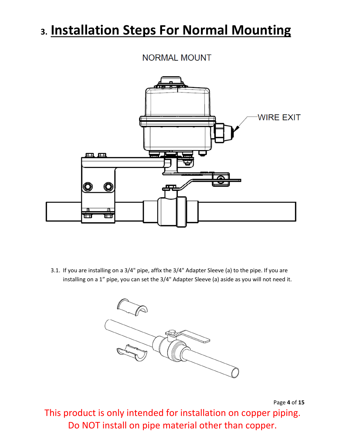
Installation Overview — Normal Mounting
Used when the 6" clearance is on the non-handle side of the valve.
- If installing on 3/4" pipe, affix the 3/4" Adapter Sleeve to the pipe (skip for 1" pipe).
- Install the Upper and Lower Mounting Brackets onto the pipe approximately 2" from the soldered end of the valve, on the non-handle side. Attach with four bolts/nuts each, finger-tight only.
- Install the Vertical Adjustment Bracket onto the Upper Mounting Bracket (finger-tight).
- Install the Horizontal Adjustment Bracket onto the Vertical Adjustment Bracket (finger-tight).
- Use the Allen wrench to seat the Manual Handle Set Screw into the Actuator Handle, and finger-tighten a nut onto the exposed bolt shaft.
- Insert the Actuator Handle into the cutout of the Horizontal Adjustment Bracket, flange on top.
- Install the Electric Actuator onto the Horizontal Adjustment Bracket so its "pigtail" faces the same direction as the Actuator Handle; secure with two nuts and tighten with the 7/16" wrench.
- Line up the stem of the Actuator Handle with the stem of the manual ball valve — front-to-back and side-to-side alignment is critical to avoid damage or injury.
- Once aligned, tighten all nuts and bolts.
- Set the Manual Handle Set Screw: turn the valve handle perpendicular to the pipe. When set correctly, the screw will be flush against the valve handle when CLOSED (it may not touch when open — this is normal). Tighten the back nut to lock the set screw position.
- Insert the Cotter Pin and Key into the open slots on the Actuator Handle (optional, used to assist manual opening).
Normal Mounting — Reference Diagrams
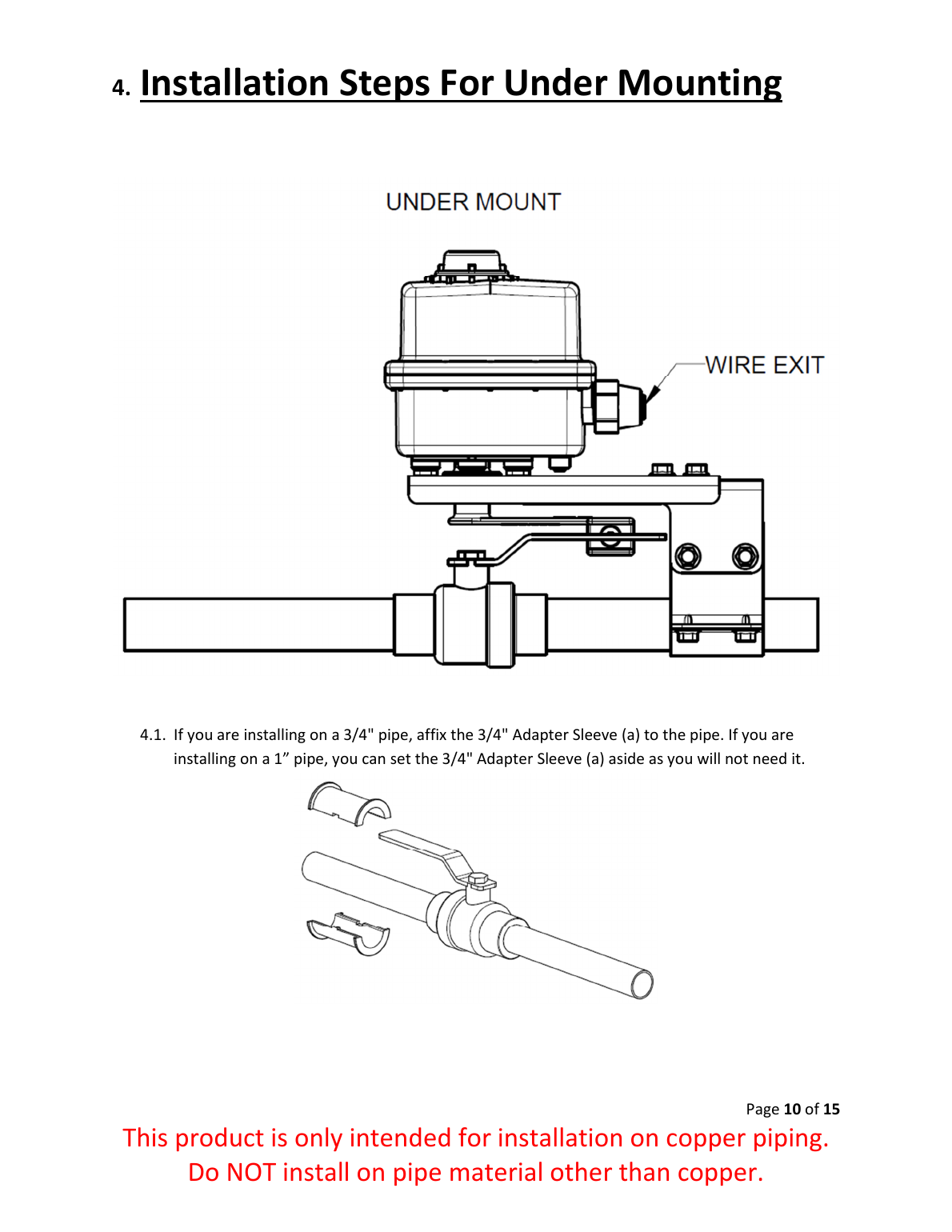
Installation Overview — Under Mounting
Used when the 6" clearance is on the handle side of the valve. The procedure mirrors Normal Mounting, with these differences:
- Install the Upper and Lower Mounting Brackets approximately 4" from the soldered end of the valve, on the handle side.
- The Actuator Handle sits underneath the Vertical/Horizontal Adjustment Brackets, and the valve handle should be able to turn freely without interference from the brackets — the valve handle sits inside the Actuator Handle bracket.
- All remaining steps (Electric Actuator installation, stem alignment, set screw adjustment, cotter pin) are the same as Normal Mounting above.
Under Mounting — Reference Diagram
Safety Notes
- Install only on copper piping — never on other pipe materials.
- Stem misalignment between the Actuator Handle and the manual ball valve can damage the actuator/valve and cause bodily injury.
- The Clamp-On Actuator is designed to close the valve in an emergency; the Cotter Pin and Key (used to assist opening) are optional. If used, verify the valve opens/closes properly after installation.