
Menu
-
-
Home Automation
- Home Automation Controllers
- Lighting & Appliance Controls
- Home Automation Sensors
-
Ventilation, Temperature & Flood Controls
- Ecovent Ventilation Controls
- Keen Home Ventilation Controls
- La Crosse Weather Reporting System
- Sensaphone Temperature/Flood
- Winland Temperature/Flood Reporting
- Ezlo Water/Flood Detection
- WaterBug Water/Flood Detection
- WaterCop Water/Flood Detection
- Specialty Water/Flood Detection
- Temperature & Heat Sensors
- Smart Irrigation Controllers
- Smart Thermostats & Ventilation Controls
- Drapery & Blind Opener Systems
- Window Opener Systems
- Door & Gate Opener Systems
- Garage Remotes & Controllers
- Smart Door Locks
-
Security
-
Home Intercom Systems
-
Specials
-
Audio/Video
-
Independent Living
-
Structured Wiring
-
More...
-
Our Brands
- 2GIG
- A&D Medical
- ABB
- Adorne
- Advanced Dynamics
- Aeotec
- Alfred
- American Hunter
- Applied Digital (ADI)
- AprilAire
- Aria Audio Technology
- Arlington Industries
- Applied Digital (ADI)
- AprilAire
- BackBoxx™
- Bellman & Symfon
- BlueSpray
- Cabletronix
- Caregiver Smart Home Automation
- Chamberlain
- Chief Manufacturing
- Cool Components
- Dakota Alert
- Danalock
- DataComm
- Data-Tronix
- D+H
- Displine
- DoorBell Fon
- DynaQuip Controls - Watercop
- Ecovent
- Elk Products
- Enbrighten
- Evolve Technologies
- Ezlo
- FirstAlert
- Flipper
- Flic
- GE
- GoControl
- Go Simply Connect
- Greenfield Direct
- Hamilton CapTel
- Home Controls In-House Exclusives
- HomeSeer
- Honeywell Home
- ION Digital
- Inovonics Wireless
- Interstate Batteries
- Intrasonic Technology (IST)
- Jasco
- KBSound
- Keen Home
- Kwikset
- La Crosse Alerts
- Letzgo Products
- Leviton
- Linear
- Linxura
- Lithe Audio
- Luxul
- Mail Chime
- MedReady
- myTouchSmart
- Napco Security Systems
- NETIO
- Nice North America
- NuTone
- OEM Systems Co.
- Presence Speakers
- On-Q By Legrand
- Open Sesame
- Optex
- Platinum Tools
- Powerline Control Systems
- Qolsys
- Resideo
- Risco Group
- Russound
- RYSE
- STI
- Sanus
- Satco
- Seco-Larm
- Security Door Controls (SDC)
- Sensaphone
- Sensative
- Serene Innovations
- Shelly
- Simply Automated, Inc. (SAI)
- Skylink
- Somfy Systems
- Sonic Alert
- Speco Technologies
- Stelpro
- Street Smart Security
- Structured Cable Products (SCP)
- TekTone
- Tripp Lite
- Truth Hardware
- U-Tec
- UCS
- USP
- Vera
- Versa
- VMP - Video Mount Products
- VSSL
- WeBoost
- Winland Electronics
- X10
- Yale
- ZTECH
- Shop By Compatibility
- Home Essentials
- Central Vac
-
Our Brands
-
- Orders
- Profile
- 1-858-693-8887
- Login
-
United States (USD $)
Add description, images, menus and links to your mega menu
A column with no settings can be used as a spacer
Link to your collections, sales and even external links
Add up to five columns
Add description, images, menus and links to your mega menu
A column with no settings can be used as a spacer
Link to your collections, sales and even external links
Add up to five columns
ELK-SWP4 — Peripheral Mounting Guide
September 08, 2026 2 min read
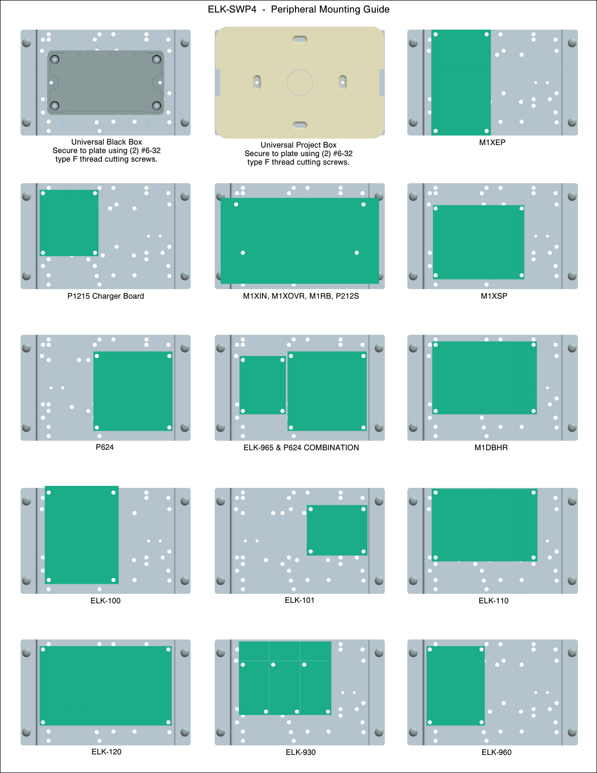
Peripheral mounting guide for the ELK-SWP4 Universal Wall/Surface Mounting Plate, showing exact placement for common Elk M1 Gold peripheral boards and accessory boxes.
Full text manual (for reference)
Peripheral mounting guide for the ELK-SWP4 Universal Wall/Surface Mounting Plate — a reference showing exactly where to position common Elk M1 Gold peripheral boards and accessory boxes on the plate.
What This Guide Covers
The ELK-SWP4 mounting plate is used to organize and secure multiple Elk peripheral boards and accessory enclosures inside an equipment cabinet or on a wall. This quick-reference sheet shows the correct mounting position and footprint for each supported component so an installer doesn't have to guess at placement or screw locations.
Components Covered on the Template
- Universal Black Box and Universal Project Box (with screw specifications)
- M1XEP (Ethernet/Internet Interface)
- M1XIN / M1XOVR / M1RB / P212S
- M1XSP (Serial Port Expander)
- M1DBHR (Dialer Board with Hardwire Receiver)
- P1215 Charger Board
- P624 (12-Output Relay Board)
- ELK-965 & P624 combination mounting
- ELK-100 / ELK-101 / ELK-110 / ELK-120 (relay/output modules)
- ELK-930 / ELK-960 (power supplies)
How to Use This Guide
- Identify which peripheral board(s) or accessory boxes you're installing (M1XEP, M1XSP, M1DBHR, P624, etc.).
- Find the matching cell in the diagram above — the highlighted (green/teal) area shows exactly where that component's mounting holes align on the SWP4 plate.
- Use the screw specifications noted for the Universal Black Box / Universal Project Box positions if you are also mounting an accessory enclosure alongside the peripheral boards.
- Lay out all planned components on the plate before drilling or fastening anything, to confirm there's no overlap when combining multiple boards (e.g. ELK-965 with P624).
Subscribe
Sign up to get the latest on sales, new releases and more …