
Chief PAC501 In-Wall Enclosure — Installation Instructions
Installation instructions for the Chief PAC501 in-wall enclosure — a recessed box for mounting swing-arm flat panel display mounts and AV accessories.
Full text manual (for reference)
Installation instructions for the Chief PAC501 In-Wall Enclosure — an in-wall recessed box for mounting swing-arm flat panel display mounts and other AV accessories, spanning three wood studs.
Important Warnings
- WARNING: failure to read, understand, and follow all instructions can result in serious personal injury, damage to equipment, or voiding of the factory warranty.
- CAUTION: must be installed and assembled by qualified service personnel in accordance with local building codes.
- WARNING: the structure to which this accessory is attached must support the combined weight of the box and all equipment, not to exceed 200 lbs (90.72 kg).
- Suitable for use in other environmental air space per Section 300.22(C) of the National Electrical Code. Maximum ambient temperature: 40–120°F (4–49°C). For use with ITE or Audio/Video equipment only.
Site Requirements
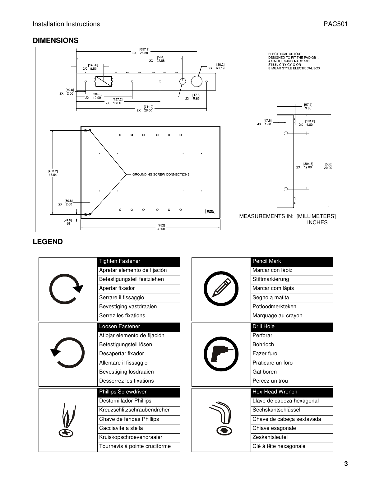
The PAC-501 is designed for in-wall installation spanning a minimum of three wood studs, 16" on center. Installing in a 2x4 wall results in nearly direct contact with the vertical studs and back wall, leaving inadequate space for electrical wires/cables, plumbing, ductwork, or insulation — locate the installation accordingly.
Installation Overview
1. Site Preparation & Frame Housing
- Identify a suitable wall location for the in-wall enclosure.
- Using a stud sensor, locate and mark studs. Center and level the housing between marked studs, then trace its outline in pencil on the drywall.
- Cut and remove drywall along the outside edge of the traced line.
- Remove the exposed portion of the center wood stud, flush with the upper and lower drywall edges.
- Cut four 8"-long support blocks from 2x4 wood and attach each to the studs with three #10 x 2-1/2" countersunk wood screws (not provided).
- If needed, cut a rectangular hole in the horizontal framing to accommodate the optional PAC-GB1 electrical box accessory, then attach the horizontal framing to each support block with two #10 x 2-1/2" countersunk wood screws.
WARNING: before cutting, drilling, or installing fasteners, always confirm the area behind mounting surfaces is free of electrical wires/cables (shock hazard) and gas/water/waste plumbing (explosion/fire hazard). Removing the center stud can reduce structural strength — consult a qualified building contractor and applicable building codes.
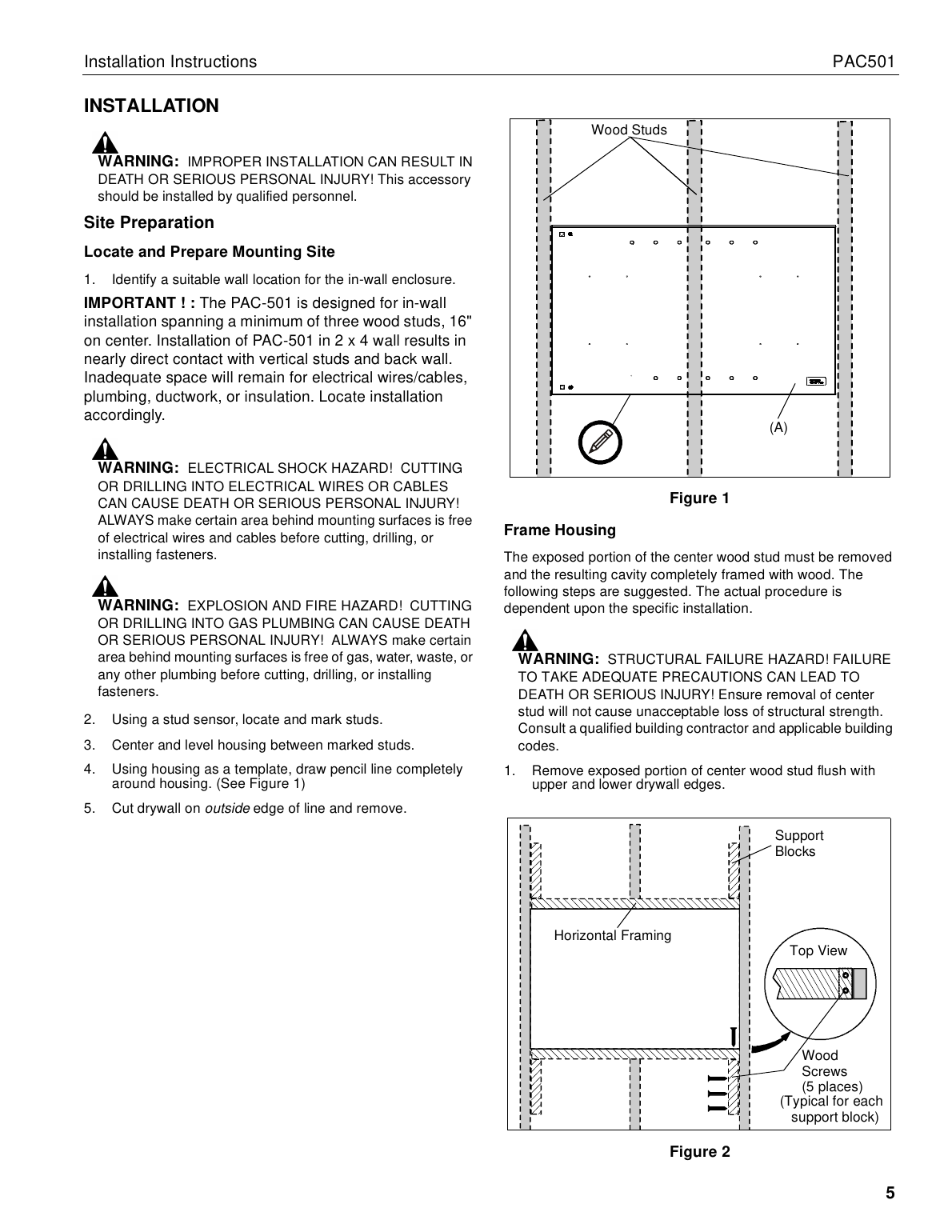
2. In-Wall Enclosure Installation
- Install the optional PAC-GB1 electrical box accessory into the PAC-501, following its included instructions.
- Connect electrical wiring and route audio/visual cables into the housing.
- Center the PAC-501 in the opening, insert it, and align the front of the box with the front face of the wall.
- Drill four 3/16" diameter pilot holes in the side studs at the side mounting holes; attach the PAC-501 to the side studs using four M7 x 50mm Allen head connector screws and mounting spacers (M4 Allen head drill bit). Note: the PAC-501 has 1/2" total clearance between the two studs — the spacers allow side-to-side adjustment.
- Drill eight 3/16" diameter pilot holes in the horizontal framing at the top and bottom mounting holes; attach the PAC-501 to the horizontal framing using eight M7 x 40mm Allen head connector screws (M4 Allen head drill bit).
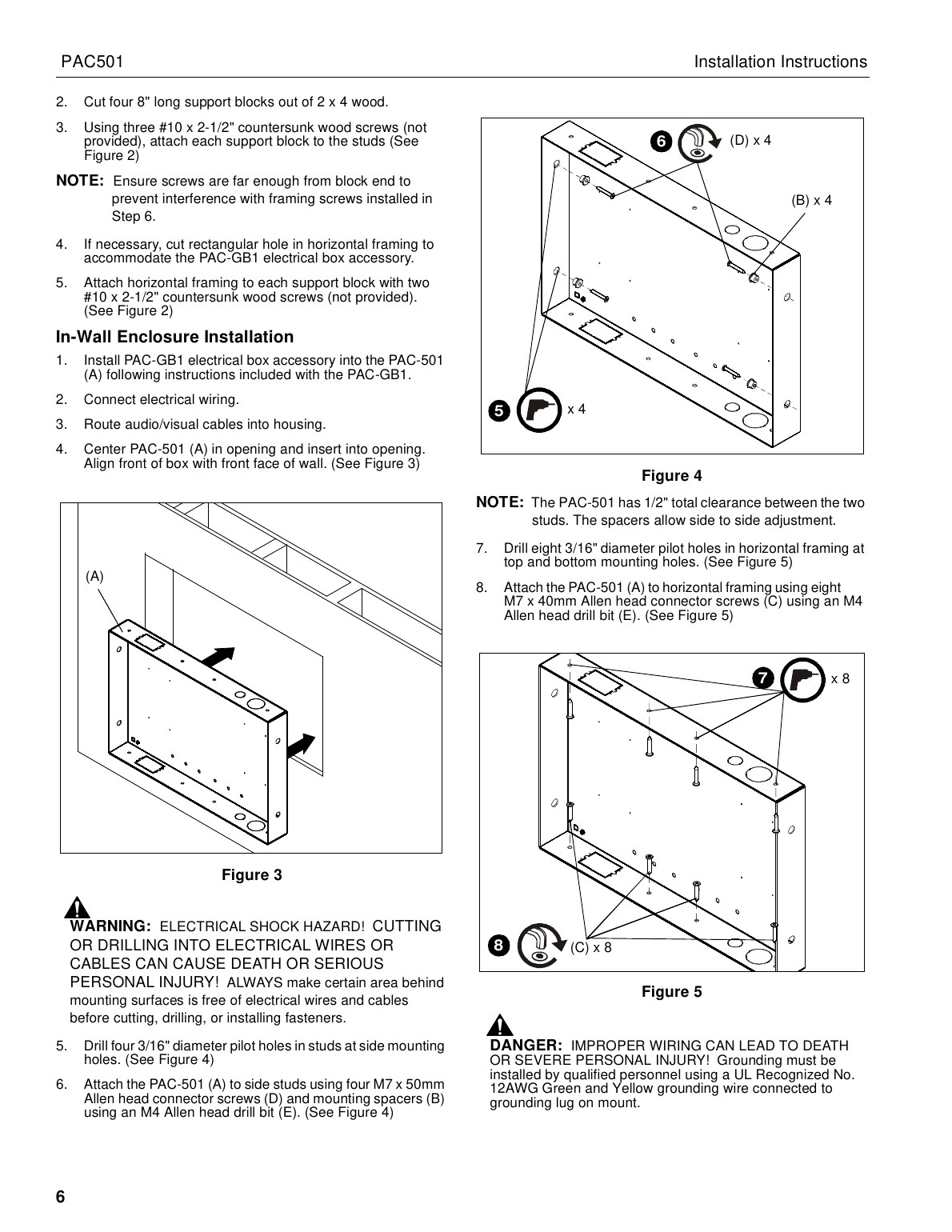
DANGER: improper wiring can lead to death or severe personal injury. Grounding must be installed by qualified personnel using a UL-Recognized No. 12 AWG green-and-yellow grounding wire connected to the grounding lug on the mount.
3. Installing the Arm Kit
Install the swing-arm mount kit following the instructions included with that kit.
Parts List
- A (1) — In-Wall Enclosure
- B (4) — Mounting Spacers
- C (8) — M7 x 40mm screws
- D (4) — M7 x 50mm screws
- E (1) — M4 Allen head drill bit
- F (6) — #8 x 1/2" screws (extras if needed for installing electrical box)
Manufacturer
Chief Manufacturing, a division of Milestone AV Technologies (a Duchossois Group Company). 8401 Eagle Creek Parkway, Savage, MN 55378. Phone: 800.582.6480 / 952.894.6280.