
Channel Vision HDM100 / HDM200R HDMI Modulator — User's Manual
User's manual for the Channel Vision HDM100/HDM200R HDMI Modulator — converts HDMI to ATSC 8VSB or QAM RF for whole-home coax distribution.
Full text manual (for reference)
User's manual for the Channel Vision HDM100/HDM200R HDMI Modulator — converts an HDMI source into ATSC 8VSB or QAM 64/256 RF output for distribution to unlimited TVs over standard coax.
Safety Instructions & Precautions
- Do not operate in high-humidity areas or expose to water/moisture.
- Disconnect from the wall outlet before cleaning; use only a light, damp cloth (no solvents).
- Do not block ventilation slots or place near/over a radiator or heat register.
- Use the enclosed ground wire, connected to your building's ground, to avoid voltage spikes or ground faults.
- Never insert objects into the unit through its openings — risk of electric shock or fire.
- Replacement parts must be manufacturer-specified; unauthorized substitutions void the warranty and may cause shock or fire.
Connections
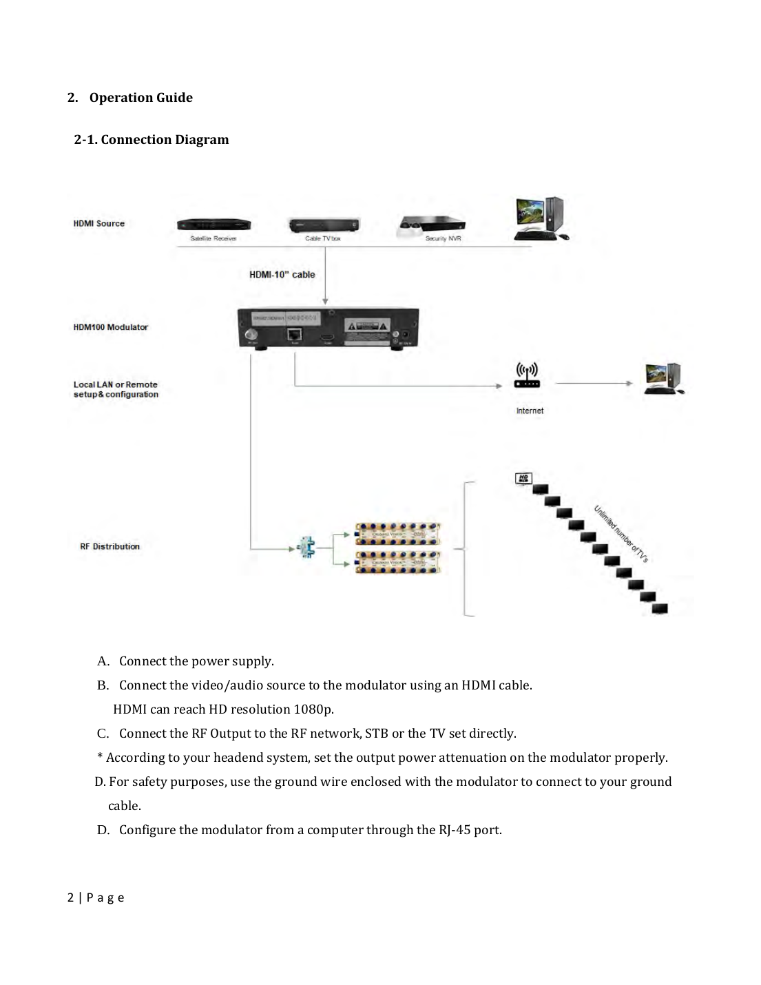
- Connect the power supply.
- Connect the video/audio source to the modulator via HDMI (supports up to 1080p).
- Connect the RF Output to the RF network, set-top box, or TV directly — set the output power attenuation on the modulator to match your headend system.
- Use the enclosed ground wire to connect to your ground cable for safety.
- Configure the modulator from a computer via the RJ-45 port.
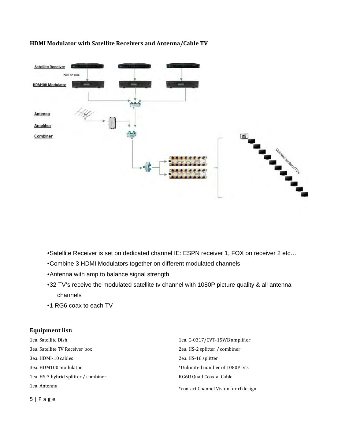
Example System: Satellite + Antenna Distribution
Multiple HDM100 modulators can be combined on different modulated channels to distribute several satellite receivers plus an off-air antenna feed to a large number of TVs over a single RG6 coax run each.
- Each satellite receiver is set to a dedicated channel (e.g. ESPN on receiver 1, FOX on receiver 2).
- Combine multiple HDM100 modulators together on different modulated channels.
- An antenna with amplifier balances signal strength alongside the modulated satellite channels.
- Up to 32 TVs can receive the modulated signal at 1080p quality plus all antenna channels, over one RG6 coax to each TV.
Front & Rear Panel
Front panel: Power LED indicator, LCD display, Up/Down/Left/Right navigation, and Enter button.
Rear panel: RF OUT (75-ohm F-type connector), RJ45 LAN port (remote configuration), HDMI digital A/V input, ground wire joint screw, and DC 12V power input.
Configuration
Settings can be configured via the front-panel control buttons or via a web browser interface (default IP 192.168.1.145).
- To unlock the unit: press and hold Right + Enter for ~5 seconds.
- Video/Audio: set Video Bit Rate (VBR range 15000–19000 Kb/s, default 19000), Y-Offset, and Major/Minor virtual channel numbers (e.g. Major=2, Minor=1 → displays as channel 2-1).
- TS Stream: set Video PID, Audio PID, PMT PID, TS ID, Service ID, and Network ID — each PID value must be unique.
- QAM: QAM 64 is recommended for overall compatibility; QAM 256 may pixelate with poorer cable delivery systems.
- RF Setup: choose Channel or Frequency mode, set frequency plan (NTSC-AIR or NTSC-CATV), and RF attenuation (0–31dB — FCC max is 15.5dBmV at the TV set; optimum signal is ~10dBmV).
- Ethernet: configure IP address, subnet, gateway, and DNS for web-based setup.
- Factory presets: 8VSB (ATSC/NTSC-AIR), B-64 (Annex B, 64QAM — factory default), B-256 (Annex B, 256QAM).
Always click "Save Changes" — unsaved settings revert to factory defaults on restart.
Troubleshooting
| Symptom | Fix |
|---|---|
| Vertical lines in picture with motion | Change video source to 720p or 1080p |
| Unable to find modulated channel | Confirm CABLE/Antenna mode on TV; scan TV channels; confirm CW Signal is disabled |
| No picture or channel found at TV | Verify HDTV has a QAM tuner; run a full channel scan in cable mode; lower unit power and check for channel conflicts |
| Image breakup | Check for channel number conflicts with other modulators/cable signals; balance RF power between modulators; lower attenuation if overdriving the tuner; change PID settings and rescan |
Specifications
| Spec | Value |
|---|---|
| HDMI Input | HDMI 1.4a, HDCP 1.4; MPEG Audio / AC3 Dolby |
| Video Encoding | MPEG-2 HD/SD Profile 2 (ISO13818-2 MP@HL), 1080p@30fps, 1920x1080 full HD |
| Modulation Type | Cable QAM / Air 8VSB; 64QAM/256QAM for Cable |
| Bandwidth | 6 MHz |
| Output Power | +95 dBuV RF cable (35dBmV), +90 dBuV RF terrestrial (30dBmV), adjustable |
| Frequency Range | 47–860 MHz |
| Cable Standard | NTSC |
| Connector | F-type female, 75 Ohms |
| Network Interface | 10M Ethernet via RJ45 |
| Power Supply | 100–240V AC, 50/60Hz → DC 12V / 2A |
Manufacturer
Channel Vision, 234 Fischer Ave., Costa Mesa, CA 92626. Phone: (714) 424-6500. techsupport@channelvision.com • www.channelvision.com