
Autoslide AS4 — Automatic Patio Door Opener Installation Instructions
Installation instructions for the Autoslide automatic patio door opening system (Model AS4), covering mounting, DIP switch programming, self-calibration, operating modes, and troubleshooting.
Full text manual (for reference)
Quick reference for installing the Autoslide automatic patio door opening system (Model AS4). This manual is highly illustrated; the diagrams below and the full downloadable PDF cover step-by-step installation, and this page summarizes the essential mounting steps, DIP switch programming, mode selection, and troubleshooting for quick reference after installation.
Before You Start
- Friction Test: Loop the supplied Friction Tester through the sliding door handle, engage the Velcro, and pull the handle at normal opening speed with the door closed, then pull it back closed. Repeat 2-3 times. If the Velcro doesn't break, the door is ready for Autoslide. If it does break, the door needs maintenance (remove obstructions, lubricate/clean the track and wheels, or replace track wheels) before installing.
- Door Stoppers: Make sure existing door stoppers are correctly positioned to stop the door at the open position — Autoslide opens the door to a maximum width of 900mm.
- Mounting Options: Three mounting positions are available depending on which way your door swings and viewing angle — Top mount over clear opening, Top mount over fixed panel, or Bottom mount underneath fixed panel. If none fit your installation, the drive unit can be re-handed (see the Re-Handing section in the full manual).
- Tools required: No. 2 flat-head screwdriver, Phillips screwdriver, marking pencil, tape measure, small flat-blade screwdriver, hack saw, utility knife, drill/driver, 1/8" (3.0mm) and 1/2" (12.0mm) drill bits.
Installation Overview
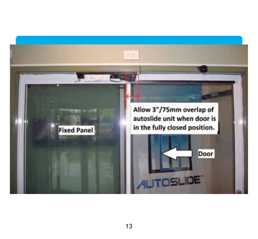
- Determine the mounting clearance — allow the specified overlap between the fixed panel and sliding door when fully closed, and the clearance needed for the drive unit mounting bracket relative to the door frame.
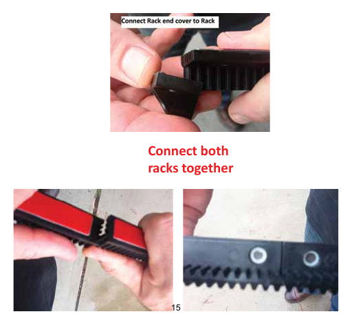
- Assemble and connect the rack sections together, attaching the rack end cover.
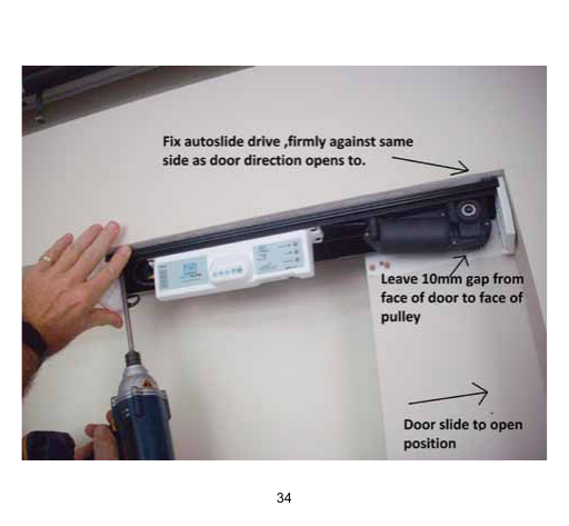
- Mount the drive unit to the head track — fix it firmly on the side matching your door's opening direction, leaving the specified gap between the door face and the pulley face.
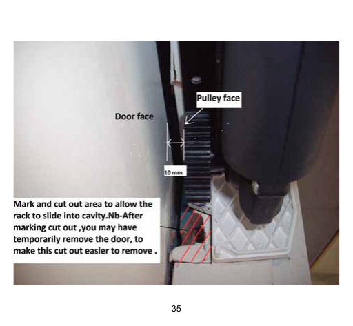
- Mark and cut the rack cavity into the top of the door face so the rack can slide into it (it can help to temporarily remove the door for easier, more accurate cutting).
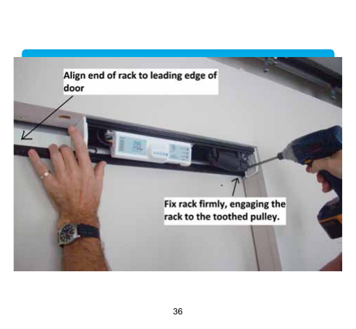
- Align the rack end with the door's leading edge and secure it so it engages properly with the toothed drive pulley.
- Install the wireless push buttons — measure 1m (3') up from the floor on each side of the door frame, ensure the surface is clean and dry, then peel and attach using the supplied double-sided tape.
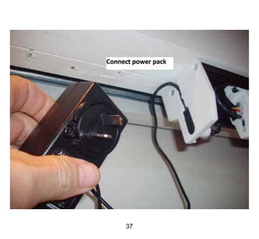
- Connect the power pack to the wall outlet and to the Autoslide control unit.
- Configure the Controller settings (see DIP Switches below), power on the drive unit, and let it complete its self-calibration ("learn") cycle.
- Install the cover: lift it up from underneath the unit (keeping the mohair clear of the control box and motor), click the end-cap tabs into the cover's groove, and push the front upward until it engages fully with the aluminum base.
Installation Reference Photos
DIP Switch Settings
| Switch | ON (back) | OFF (forward) |
|---|---|---|
| 1. Direction | Left opening | Right opening (toggle back and forth to erase memory and re-learn open/close cycle) |
| 2. Slam Shut | Helps overcome weather seals | Normal operation |
| 3. Pet Learn | Toggle to start pet opening size learn cycle | — |
| 4. External Lock | ON if wiring external N/C fail-secure or N/O fail-safe lock | — |
| 5. Less Power | Max 75% open power | Normal operation |
| 7. Toggle mode | Activate to open, activate to close | Normal mode |
| 8. Beeper | Enabled | Disabled |
Powering On & Self-Calibration
- Confirm DIP switch settings, then switch the main isolator to the down (ON) position. Caution: the door will begin to move without warning.
- The LED display flashes and the door slowly closes, then slowly opens fully, then closes again with a slight speed increase, then opens once at full speed, then closes — once the LED stops blinking and turns solid green, the learn cycle succeeded. Autoslide has now memorized your door's opening width, weight, and friction, and calibrated the power needed to move it smoothly.
- If the door opens instead of closing when first powered up, flip DIP switch 1 to the opposite position (power still on) to reverse the closing direction.
- If the door doesn't complete the learn cycle correctly, switch the isolator off, check DIP switch 1's direction setting, and switch back on to retry.
- Power interruptions don't erase your settings — when power resumes, the door completes its close/pause/reopen learn sequence again automatically.
Operating Modes
Cycle modes with successive presses of the Mode button next to the LED display:
- Automatic (green LED) — opens on sensor trigger, closes after the preset dwell time.
- Hold Open (blue LED) — opens and stays open until another mode is selected.
- Standby (red LED) — manual operation only; Autoslide will not drive the door.
- Pet (yellow LED) — opens only to the learned pet-width opening when a pet sensor triggers (only appears once a pet width has been set).
Setting a Pet Opening Width
- Toggle DIP switch 3 (Pet Learn) — the door closes (with a brief delay if already closed).
- The door then slowly opens; stop it (preferably with your foot — keep hands/objects clear) at the desired pet-width opening.
- The door closes again; once fully closed, Autoslide returns to Automatic mode (green LED) and Pet mode becomes available.
- Test by pressing the pet sensor button; if the width is wrong, repeat from step 1.
Troubleshooting
| Symptom | Cause & Solution |
|---|---|
| Door doesn't open fully after learn cycle | Incomplete learn cycle — remove cover, power off, close door manually, power back on, retest after the learn cycle completes, refit cover. |
| Door reopens after every close cycle | Rack & pinion have skipped teeth — check/adjust gear engagement, then redo the learn cycle as above. |
| Door moves very slowly / struggles | Door weight configuration incorrect — enable DIP switch 5 or 6 to increase power output. |
| Can't overcome starting friction | Door lock/catch engaged (release it — Autoslide only runs when unlocked), or heavy weather seals/excess friction (enable DIP switch 2 for more starting power). |
| Door stops mid-cycle; blue+red+yellow lights all illuminate | Over-current trip from excessive load — investigate and clear sources of friction. |
| Excessive noise / labored operation | Rack and pinion meshed too tightly — ensure a slight gap along the full rack length; adjusting door height via the wheels may be easier than removing the rack. |
| Door opens at random | RF interference (clear and re-learn remotes via the controller's learn button) or IR sensors too sensitive (reduce the sensitivity dial under the sensor covers). |
| Door tries to open but doesn't | Rack & pinion skipped teeth — check/adjust engagement and redo the learn cycle. |
Warranty
12-month warranty against faulty material or workmanship from date of purchase, covering repair or replacement at Autoslide's premises, provided the unit was installed per the supplied instructions on a free-sliding domestic patio door and the warranty claim is made through the original retailer with proof of purchase. Void if abused, used outside spec, rewired outside factory settings, or altered by the purchaser. Battery warranty follows the original battery manufacturer's terms.
Support: support@autoslide.com.au | Toll Free (Australia): 1300 AUTOSLIDE | USA: (212) 901-4141 | International: +1 866 967 3669