
Aeotec Z-Wave Plus illumino On/Off Wall Switch (ZWA038-A) — User Manual
Engineering specifications and installation guide for the Aeotec Z-Wave Plus illumino On/Off Wall Switch (ZWA038-A), Gen7, including wiring diagrams and configuration parameters.
Full text manual (for reference)
Engineering specifications and installation guide for the Aeotec ZWA038-A Z-Wave Plus illumino On/Off Wall Switch — a security-enabled Z-Wave Plus smart wall switch, Gen7.
Overview
This product operates in any Z-Wave™ network alongside other Z-Wave Plus™ certified devices from any manufacturer. All non-battery-operated nodes act as repeaters, retransmitting radio frequency signals around obstacles and dead spots to boost network reliability. The ZWA038-A is security-enabled — a Security 2 (S2) enabled Z-Wave Plus™ controller is required to fully utilize the product.
Wiring Diagrams
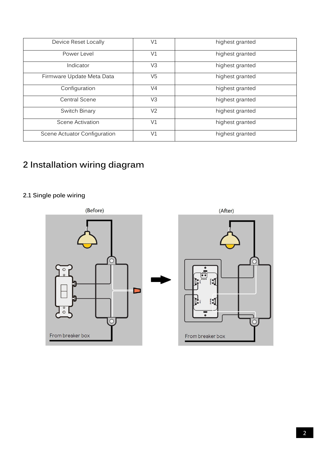
Always turn off power at the breaker before wiring.
Z-Wave Network Operation — Action Button Functions
| Function | Action | Description |
|---|---|---|
| Inclusion | 1× tap (out of network) | Sends NIF for network pairing (white LED quick flashes; solid green for 2s on success) |
| Central Scene (1×) | 1× tap (in network) | Triggers Central Scene 1× tap scene |
| Central Scene (2×) | 2× tap (in network) | Triggers Central Scene 2× tap scene |
| Exclusion | 3× tap (in network) | Sends NIF for network unpairing (purple LED flashes) |
| Central Scene (3×) | 3× tap (out of network) | Triggers Central Scene 3× tap scene |
| Toggle Parameter 86 (top button) | 4× tap | Toggles indicator brightness 0–100% |
| Toggle Parameter 84 (top button) | 5× tap | Toggles indicator color for output, 0–9 |
| Toggle Parameter 85 (top button) | 6× tap | Toggles indicator color for scene, 0–9 |
| Toggle Parameter 83 (top button) | 7× tap | Toggles LED indicator function, 0–2 |
| Toggle Parameter 121 (bottom button) | 4× tap | Toggles output control, 0–3 |
| Toggle Parameter 122 (bottom button) | 5× tap | Toggles paddle button function, 0–2 |
| Toggle Parameter 20 (bottom button) | 6× tap | Toggles power-restore status, 0–2 |
| Toggle Parameter 120 (bottom button) | 10× tap | Toggles external switch type, 0–2 |
| Central Scene hold/release | Press & hold 1–15s / release | Triggers hold and release scene events |
| (Nothing) | Press & hold 16–19s | Flashes red LED rapidly |
| Factory Reset | Press & hold 20s | Sends gateway "Reset Device Locally"; when LED turns blue, release and tap again within 2s to confirm and start the reset process |
Note: Full functionality requires a Security 2 (S2)-enabled Z-Wave controller.
Association Groups
Supports 5 association groups, each with up to 5 associated nodes.
| Group | Name | Function |
|---|---|---|
| 1 | Lifeline | Device Reset Locally, Indicator Report, Switch Binary Report, Basic Report, and Central Scene notifications |
| 2 | Top button set ON/OFF | Basic Set / Switch Binary Set on top button press |
| 3 | Bottom button set ON/OFF | Basic Set / Switch Binary Set on bottom button press |
| 4 | External switch set ON/OFF | Basic Set / Switch Binary Set on external switch press |
| 5 | Top and bottom button set ON/OFF | Basic Set / Switch Binary Set on either button press |
Key Configuration Parameters
| # | Name | Description | Default |
|---|---|---|---|
| 20 | Power Restore | Status after power failure (0=OFF, 1=ON, 2=last known state) | 2 |
| 40 / 41 | Auto Turn Off / On Timer | Auto-toggle timer, 0–65535 sec (0=disabled) | 0 (disabled) |
| 80 | Instant Status Report | Command used for status reports (0=none, 1=Basic Report, 2=Binary Switch Report) | 2 |
| 82 | Association Control Settings | Command sent to association group (1=Basic Set, 2=Binary Switch Set) | 1 |
| 83 | LED Indicator Settings | 0=disabled, 1=momentary blink, 2=LED follows output status | 2 |
| 84 / 85 | LED Color (Output / Scene) | 0–9: disabled, red, blue, green, pink, cyan, purple, orange, yellow, white | 9 / 2 |
| 86 | LED Brightness | 0=disable, 1–100% | 60 |
| 119 / 120 | External (3-Way) Switch Scene / Type | 119: enable/disable scene function; 120: 0=toggle only, 1=NO momentary, 2=NC momentary | 1 / 0 |
| 121 | Output Control | 0=disabled, 1=local control, 2=central scene, 3=local + central scene | 3 |
| 122 | Button Function | 0=up/ON down/OFF, 1=down/ON up/OFF, 2=toggle (either direction) | 0 |
| 123 | Report Behavior | Behavior for status report/LED indicator when output is disabled | 0 |
All parameters reset to factory defaults after a device reset.
Security
This is a security-enabled Z-Wave Plus product supporting S2 encrypted communication. It auto-switches to security mode when included with a security controller. Supported security levels: S2 Unauthenticated and S2 Authenticated (S0 is not supported).
SmartStart
SmartStart-enabled products can be added to a Z-Wave network by scanning the QR code on the bottom of the product with a SmartStart-capable controller — no further action needed; the device is added automatically within 10 minutes of being powered on near the network.
Specifications
| Power Supply | AC 120V, 60Hz |
| Max Amperage | 15A |
| Max Wattage | 1800W (US) |
| Max Standby Power | 0.8W |
| LED | RGB LED |
| Communication Frequency | 908.40MHz, 916.00MHz (US) |
| Communication Range | Up to 70m+ indoors (line of sight) / 150m outdoors |
| Certification | Z-Wave Plus v2 with SmartStart |
| Operational Temperature | 0–40°C / 32–104°F |
| Operating Humidity | 8% to 80% |