
ABB-Welcome M25102 Series — Outdoor Station Quick Reference Guide
Quick reference guide for the ABB-Welcome M25102 series modular outdoor door entry station — covers module wiring, addressing, system settings, and mounting.
Full text manual (for reference)
Quick reference guide for the ABB-Welcome M25102 series Outdoor Station — a modular door entry/intercom station family (M25102xC, M25102xA-x, M25102xPx, M25102xK-x, M25102xCR, M25102xDN) supporting audio, camera, push-button, keypad, and display/card-reader modules. This manual is highly illustrated; the diagrams below and the full downloadable PDF cover detailed wiring and mounting instructions.
Critical Safety Warnings
- Electric voltage risk: Work on the 100–240V supply system may only be performed by authorised electricians. Disconnect mains power before installation or disassembly.
- Low-voltage and 100–240V cables must never be installed together in a flush-mounted socket — a short circuit could put a 100–240V load on the low-voltage line.
- Only install if you have the necessary electrical engineering knowledge and experience — incorrect installation endangers life and property, including fire risk.
- Apply the "five safety rules" (DIN VDE 0105 / EN 50110): disconnect from power source, secure against reconnection, verify no voltage, connect to earth, cover/barricade adjacent live parts.
System Modules
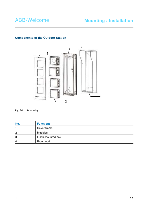
The outdoor station is built from stackable modules, each with its own terminal block:
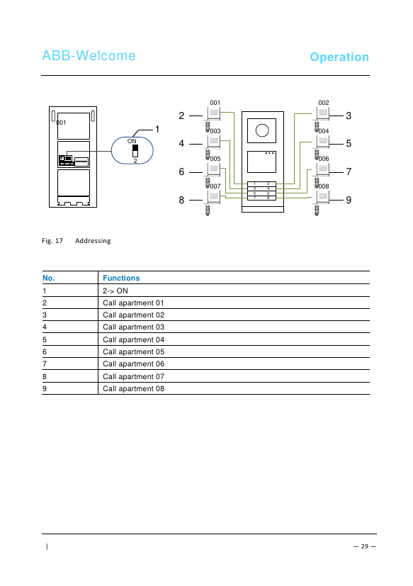
- Audio module — core module with call pushbuttons, status LEDs, floating door-opener output (COM-NC-NO, 30VAC/DC 1A), Lock-GND output (18V 4A impulsive / 250mA holding), bus connection (a-b), and an address rotary switch (1–9). Adjustable speaker volume and door lock release time (1–10s).
- Camera module — supports an additional analog camera (1Vp-p 75Ω CVBS), up to ~50m via coax or ~10m via other cable types; PAL/NTSC jumper selectable; can also be used as a detached camera.
- Push button module — call buttons numbered top-to-bottom, left-to-right in double-column mode; button 1/2 can be configured for lighting switch or guard-unit call.
- Keypad module — numeric keypad for physical address dialing and system settings.
- Display & card reader module — adds an LCD display and proximity card reader for advanced access control.
- Nameplate module — printable resident name labels via the Welcome configuration software.
Terminal / Push-Button Configuration Jumpers (Audio Module)
- Jumper 11: rotary switch sets the outdoor station's address (1–9)
- Jumper 12: enables/disables feedback tones for push buttons
- Jumper 13: single-column vs. double-column push button layout
- Jumper 14: configures 1st/2nd push button function — call indoor station, switch on lighting, or call guard unit (all 4 combinations supported)
- Jumper 15: speaker volume
- Jumper 16: door lock release time (1–10 seconds, for the Lock-GND output)
Operation — Keypad Outdoor Station (System Settings)
Default system password: 345678. Enter #* [system password] # to open the System Settings menu, then navigate: Configurations, Access Control, Contact, Settings.
- Device type: set as Outdoor Station (default) or Gate Station.
- Call mode: by Physical Address, or by Logic Code (1–8 digits).
- Door open code: default 123456 (6–8 digits), modifiable at the outdoor station; up to 6,000 passwords can be stored system-wide (residents can also set their own via indoor stations).
- Proximity cards: up to 3,000 cards can be registered per outdoor station (register, delete individually, or delete all).
- Contacts: up to 3,000 names (24 alphanumeric characters each), addressable by user name or logic address; add, modify, delete individually, or clear all.
- Date & time, door open time (1–10s, default 3s), voice message on/off (requires speech-synthesis audio module M251024A-.), language selection, welcome message (max 64 characters), Wiegand output (26-bit or 34-bit), and which lock (1st: Lock-GND, or 2nd: NC-NO-COM) releases on card swipe are all configurable from this same menu tree.
Technical Data
| Operating temperature | -40°C to +70°C |
| Protection (cover frame assembled) | IP54 |
| Power supply, door opener (Lock-GND) | 18V, 4A impulsive, 250mA holding |
| Floating output, door opener (COM-NC-NO) | 30V AC/DC, 1A |
| Single-wire / fine-wire clamps | 2 x 0.28mm² – 2 x 1mm² |
| Bus voltage | 20–30V |
Mounting & Installation
- Terminate all wiring branches via a connected bus device (indoor station, outdoor station, or system device).
- Don't install the system controller directly next to the bell transformer or other power supplies (interference risk).
- Don't run system bus wires together with 100–240V wires, and don't share cables between door-opener wiring and system bus wiring.
- Use only two wires for the system bus in a multi-core cable, and never route incoming/outgoing bus wiring inside the same cable when looping.
Environment
All ABB packaging materials and devices bear proper disposal markings. Dispose of packaging and electronic devices via authorized collection depots per EU Directive 2002/96/EG (WEEE) and 2002/95/EG (RoHS), and the EU-REACH ordinance (EG No. 1907/2006). Do not dispose of as unsorted municipal waste.