
ABB-Welcome M2233x 7" Video Hands-Free Indoor Station — User Manual
Quick reference for the ABB-Welcome M2233x-x 7" Video Hands-Free Indoor Station.
Full text manual (for reference)
Quick reference for the ABB-Welcome M2233x-x 7" Video Hands-Free Indoor Station — a touchscreen intercom panel for the ABB-Welcome door communication system. This manual is highly illustrated with on-screen menu diagrams; the images below and the full downloadable PDF cover every settings screen in detail. This page summarizes safety, control elements, key settings screens, cleaning, and technical/installation reference.
Critical Safety Warning
Electric voltage! Risk of death and fire due to electrical voltage of 100-240 V.
- Work on the 100-240V supply system may only be performed by authorized electricians.
- Disconnect the mains power supply prior to installation and/or disassembly.
Intended use: the M2233x-x is an integral part of the ABB-Welcome door communication system and operates exclusively with components from that system. Must be installed in dry indoor rooms only.
Control Elements
| No. | Function |
|---|---|
| 1 | 7" touch screen |
| 2 | Communication button — press to activate/end a call, or (in standby) to set up voice/video with the default outdoor station |
| 3 | Unlock button — opens the door at any time; auto-unlock LED shows solid if auto-unlock is active, flashes rapidly if door has been open too long (requires a connected door sensor) |
| 4 | Mute button — mute ringtone for this station (press) or all stations in the apartment (hold); reject an incoming call; mute the mic during a conversation |
| 5 | Programmable button — default releases the 2nd lock (COM-NC-NO on an outdoor station); can be reassigned to call a guard unit, make an intercom call, etc. |
| 6 | History button — displays History records; press during a video call to take a manual snapshot |
| 7 | System setting button — opens the system settings menu |
Key Control Actions
Surveillance
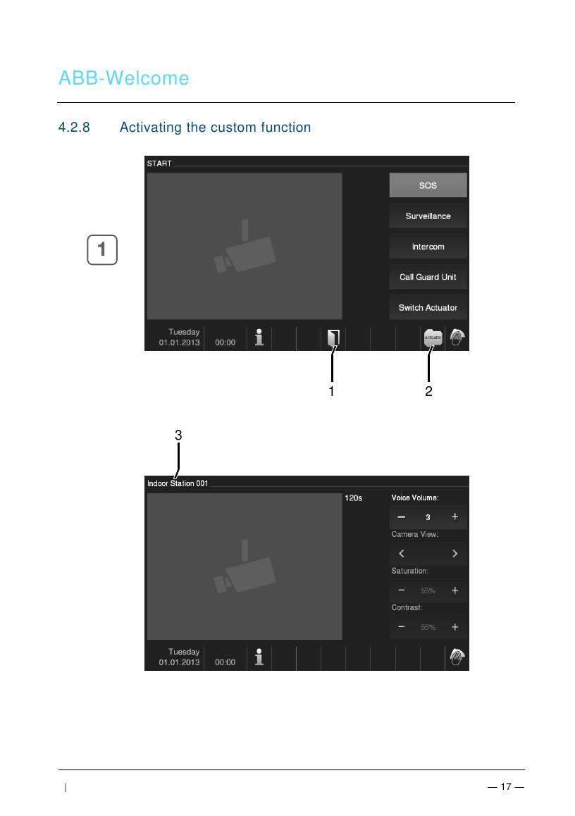
Touch "Surveillance" to view the default outdoor station's camera (video only at first — press the communication button to activate voice). Controls include camera designation, volume (+/-), camera selection (if multiple outdoor stations/cameras), and display saturation/contrast.
Intercom
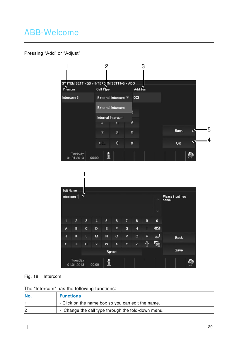
Touch "Intercom" to open the call menu, showing each contact's name, address, and type (internal = same apartment, external = different apartment). Intercom call lists must first be configured under System Settings > Intercom Setting.
Calling a Guard Unit
Touch "Guard unit" to call the guard station directly, with volume control available during the call.
Events, Snapshots & History
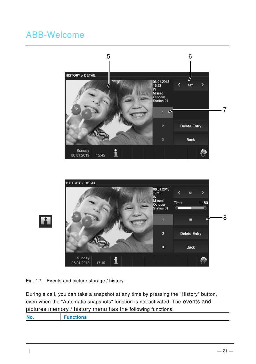
The panel automatically records the last 100 events (older ones are overwritten). If "Automatic snapshots" is enabled, three pictures are taken each time the doorbell rings, ensuring at least one optimum shot; snapshots can also be taken manually at any time during a call by pressing the History button. Individual entries or the whole list can be deleted, and snapshots can be archived to an SD card (SD/SDHC). Intercom calls can be added to a blacklist to block unwanted callers, and any recorded voice message can be played back from the details window.
System Information
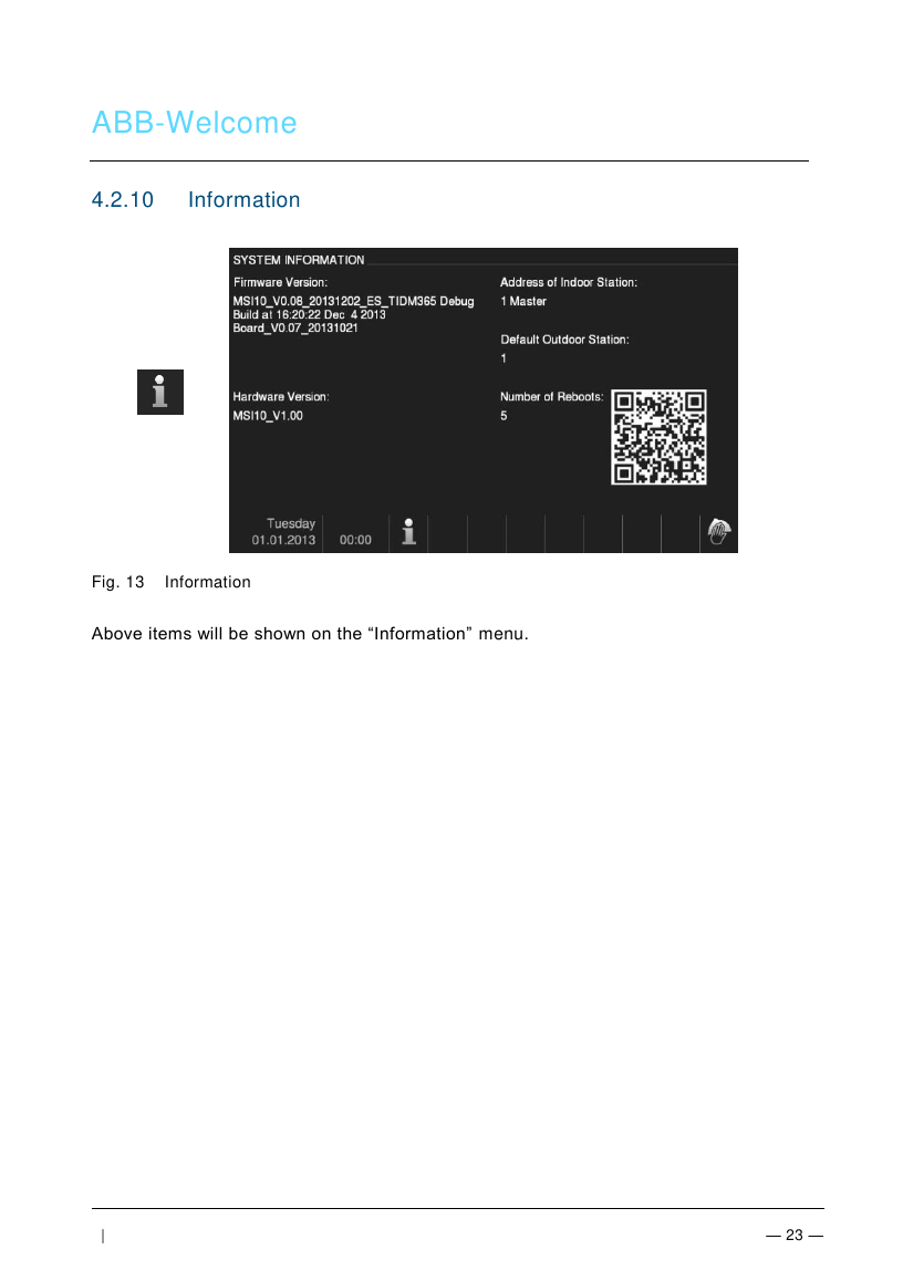
The Information screen shows the indoor station's address, its default outdoor station, master/slave role, and current software/firmware version — useful for troubleshooting and support calls.
Settings — Setup Menu
| Function | Detail |
|---|---|
| Automatic Snapshots | Three snapshots automatically taken and stored to History when the bell is pressed. Can only be activated when the automatic door opener is deactivated (to avoid excessive snapshots during busy periods). |
| Door Status Check | If enabled, the outdoor station's door sensor sends an alarm to the indoor station when the door is left open too long. |
| Key Illumination | Illuminates keys during operation when enabled; otherwise keys stay unlit. |
| Indoor Station Address | Only editable when the last two rotary switches are set to "00"; range 001-250. |
Firmware Update
- Get the new firmware version from your electrical installer and copy it onto an SD card.
- Insert the SD card into the card slot on the indoor station.
- Select "Firmware Update," then "Updating" to execute.
- Confirm the popup with "Yes."
Cleaning
Caution: the screen surface can be damaged by hard or sharp objects — use only your finger or a plastic stylus, never a hard/sharp object. Clean surfaces with a soft cloth and commercially available glass cleaner; never use abrasive cleaning agents.
Adjusting the Device — Terminal Resistor & Address Switches
| No. | Function |
|---|---|
| 1 | Station selector switch — sets the address of the default outdoor station |
| 2 | X10 / X1 selector switches — set the tens/units digits of the indoor station address (hundreds digit requires the system menu) |
| 3 | Master/Slave switch — only one indoor station per apartment should be set to Master ("M/S on"); all others must be Slave ("M/S off") |
| 4 | Terminal resistor switch — in video or mixed audio/video installations, set "RC on" on the last device in the line |
Connections: terminal 1 is for the door bell push-button; terminal 2 connects to the system controller (or, with multiple indoor stations, the internal bus).
Technical Data
| Spec | Value |
|---|---|
| Display resolution | 800 x 480 |
| Display size | 17.8 cm (7") |
| Operating temperature | -10°C to +55°C |
| Storage temperature | -40°C to +70°C |
| Protection Rating | IP 30 |
| Single-wire clamps | 2 x 0.28 mm² – 2 x 0.75 mm² |
| Fine-wire clamps | 2 x 0.28 mm² – 2 x 0.75 mm² |
| Bus voltage | 20-30 V |
| Size | 155 x 218 x 29 mm |
Mounting / Installation
The device must only be installed by an authorized electrician following the "five safety rules" (DIN VDE 0105, EN 50110): disconnect power, secure against reconnection, verify no voltage, connect to earth, and cover/barricade adjacent live parts. General installation guidance:
- Terminate all wiring branches via a connected bus device (indoor station, outdoor station, or system device).
- Do not install the system controller directly next to the bell transformer or other power supplies (interference risk).
- Do not run system bus wiring together with 100-240V wires, or share cables between door opener wiring and the system bus.
- Use only two wires for the system bus within a four-core or multi-core cable; never route incoming/outgoing bus or internal/external bus inside the same cable.
Mounting steps: open the housing by pulling the bottom clamp; fix the bottom part to a level wall surface or flush-mounted box (DIN 49073-1); wire per the connection diagram; set outdoor station address, indoor station address, and master/slave + terminal resistor switches; then latch the upper housing onto the bottom part. A desktop bracket mounting option is also available.