
Yale Real Living Assure Lock Push Button Deadbolt (YRD216) — Installation & Programming Instructions
Full installation and programming instructions for the Yale Real Living Assure Lock Push Button Deadbolt (YRD216), including menu tree and troubleshooting.
Full text manual (for reference)
Installation and programming instructions for the Yale Real Living® Assure Lock™ Push Button Deadbolt (YRD216) — an ASSA ABLOY brand keypad deadbolt with optional network module support. This manual is a scanned illustrated instruction sheet; the images below are the full original pages.
Warning: Failure to follow these instructions could result in damage to the product and void the factory warranty.
Tip: Download the BILT App for 3D interactive installation instructions and to register your product.
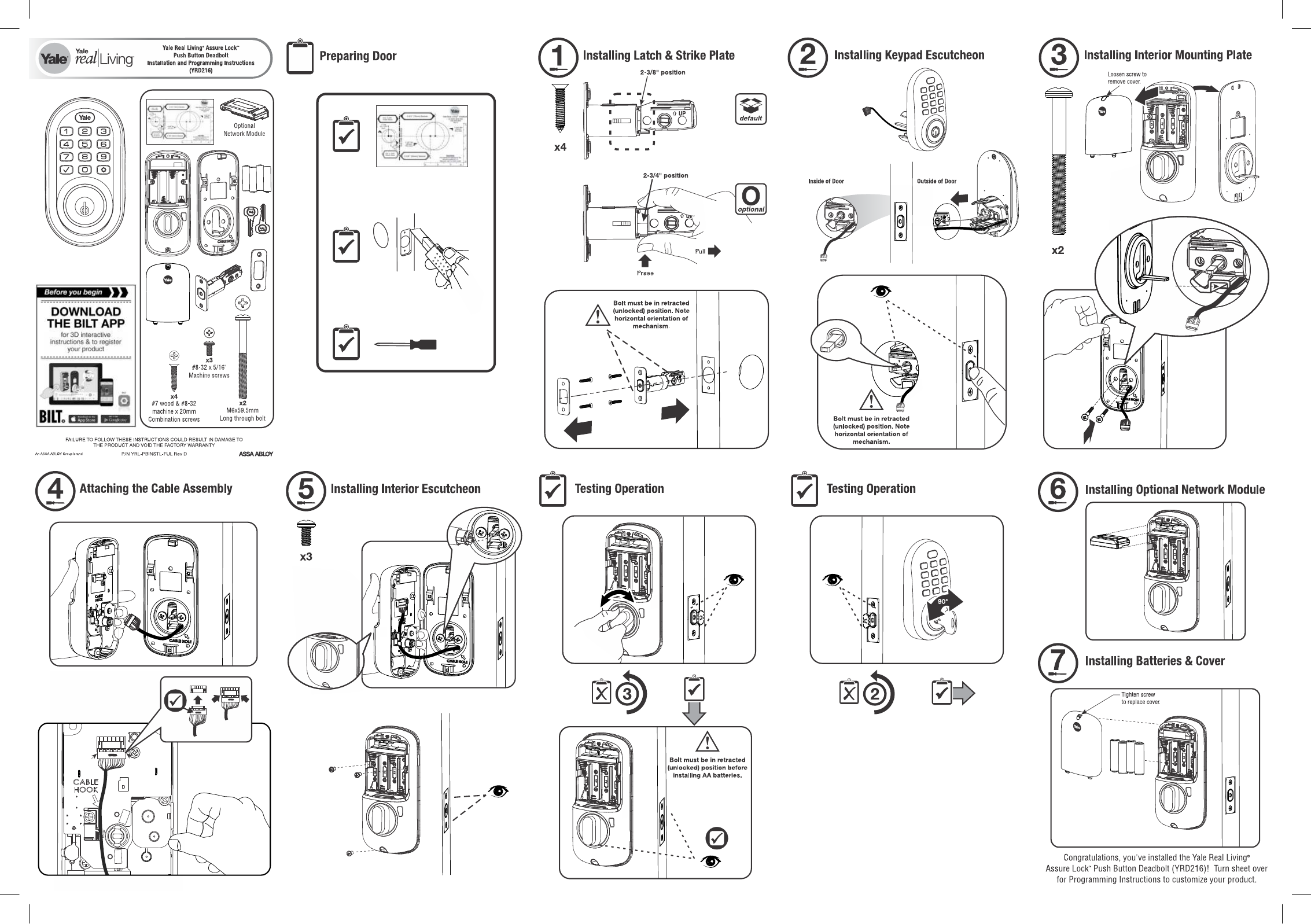
Installation Overview
- Install the latch and strike plate (4 screws) at the 2-3/8" default or 2-3/4" optional backset, with the bolt retracted (unlocked).
- Install the keypad escutcheon on the outside of the door, bolt retracted.
- Install the interior mounting plate (loosen the cover screw first) with the 2 long through bolts.
- Attach the cable assembly, observing correct cable hook orientation.
- Install the interior escutcheon with 3 screws, routing the cable hook correctly.
- Test operation before installing AA batteries — bolt must be retracted.
- Install the optional network module if applicable.
- Install batteries and replace the cover.
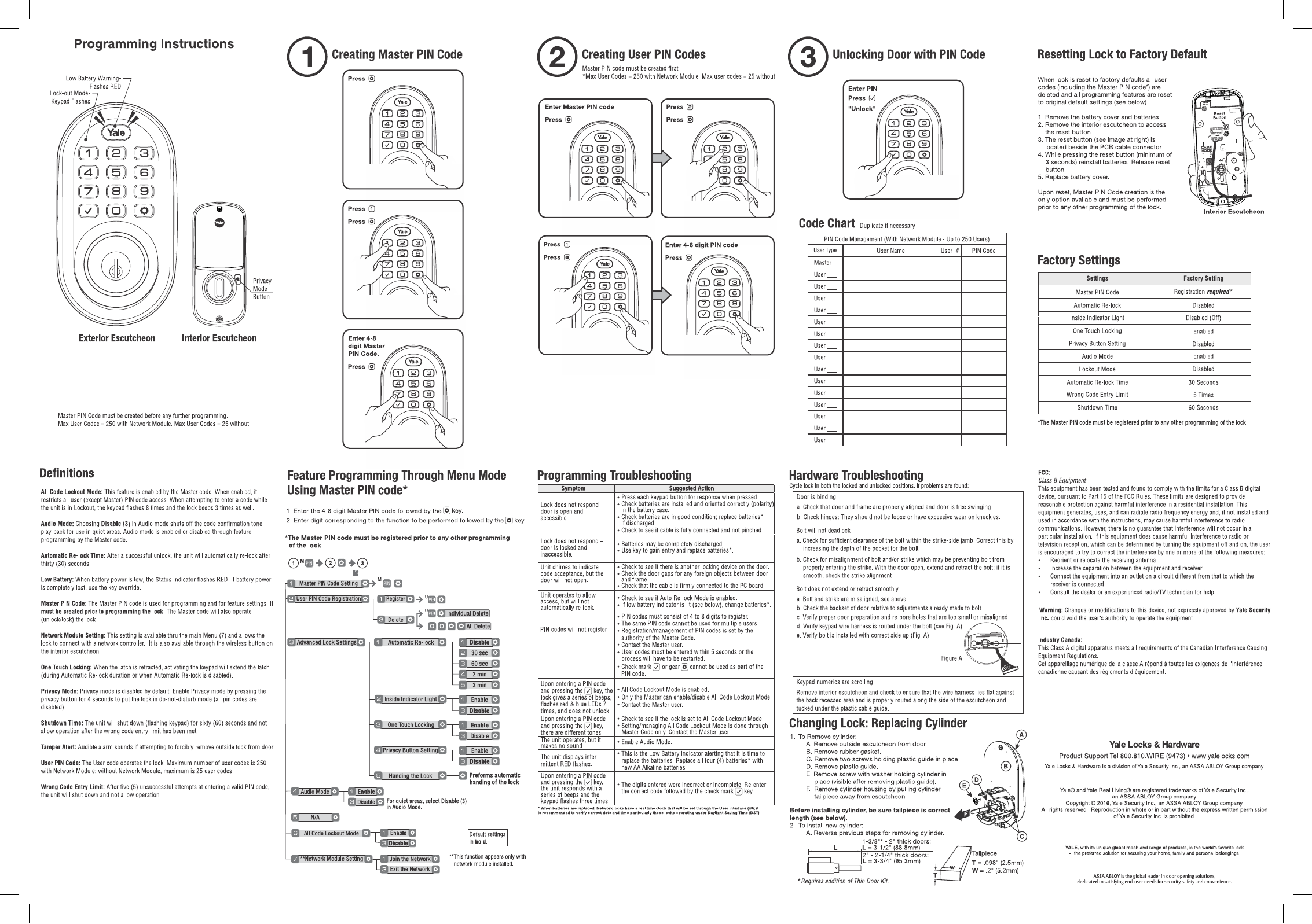
Programming Instructions
A Master PIN Code must be created before any further programming. Max user codes = 250 with the Network Module, or 25 without.
Step 1: Creating the Master PIN Code
Press ⚙ (gear) → Press ⚙ again → Press 1 → Press ⚙ → Enter 4-8 digit Master PIN Code → Press ⚙
Step 2: Creating User PIN Codes
(Master PIN must exist first) Enter Master PIN → Press ⚙ → Press 1 → Press ⚙ → Enter 4-8 digit PIN code → Press ⚙
Step 3: Unlocking with a PIN Code
Enter PIN → Press ✓ (Unlock)
Resetting to Factory Default
Resetting deletes all user codes (including Master) and restores default settings.
- Remove the battery cover and batteries.
- Remove the interior escutcheon to access the reset button (located beside the PCB cable connector).
- Press and hold the reset button (minimum 3 seconds) while reinstalling batteries, then release.
- Replace the battery cover.
After reset, Master PIN Code creation is the only available option and must be performed before any other programming.
Factory Settings
| Setting | Factory Default |
|---|---|
| Master PIN Code | Registration required |
| Automatic Re-lock | Disabled (default 30 seconds when enabled) |
| Inside Indicator Light | Disabled |
| One Touch Locking | Enabled |
| Privacy Button Setting | Disabled |
| Audio Mode | Enabled |
| Lockout Mode | Disabled |
| Wrong Code Entry Limit | 5 times |
| Shutdown Time | 60 seconds |
Feature Programming Menu (via Master PIN)
Enter the 4-8 digit Master PIN followed by ⚙, then enter the digit for the desired function followed by ⚙. Default settings shown in bold below.
- 1 — Master PIN Code Setting: M PIN + ⚙
- 2 — User PIN Code Registration: 1 Register (PIN + ⚙); 3 Delete (PIN → Individual, or ⚙⚙⚙ for All Delete)
-
3 — Advanced Lock Settings:
- 1 Automatic Re-lock: 1 Disable, 2 30 sec, 3 60 sec, 4 2 min, 5 3 min
- 2 Inside Indicator Light: 1 Enable, 3 Disable
- 3 One Touch Locking: 1 Enable, 3 Disable
- 4 Privacy Button Setting: 1 Enable, 3 Disable
- 5 Handing the Lock (automatic handing)
- 4 — Audio Mode: 1 Enable, 3 Disable (select Disable for quiet areas)
- 7 — Network Module Setting (appears only with module installed): 1 Join the Network, 3 Exit the Network
- 8 — All Code Lockout Mode: 1 Enable, 3 Disable
Key Definitions
- All Code Lockout Mode: Enabled by the Master code; restricts all non-Master PIN access. Keypad flashes 8 times and beeps 3 times if a code is entered while locked out.
- Automatic Re-lock Time: Unit re-locks 30 seconds after a successful unlock (default).
- Low Battery: Status indicator flashes RED. Use key override if power is completely lost.
- Privacy Mode: Press the privacy button for 4 seconds to enter do-not-disturb mode (disables all PIN codes).
- Shutdown Time: Unit shuts down for 60 seconds (flashing keypad) after the wrong-code entry limit is reached.
- Tamper Alert: Audible alarm sounds if forcible removal of the outside lock is attempted.
Programming Troubleshooting
| Symptom | Suggested Action |
|---|---|
| Lock does not respond (door open/accessible) | Check keypad response, battery polarity/condition, and cable connection. |
| Lock does not respond (door locked/inaccessible) | Batteries may be discharged — use key to gain entry and replace batteries. |
| Chime sounds but door won't open | Check for another locking device, door gap obstructions, or a loose PC board cable. |
| Won't automatically re-lock | Check Auto Re-lock Mode is enabled; change batteries if low-battery indicator is lit. |
| PIN codes won't register | Codes must be 4-8 digits, unique per user, entered within 5 seconds; contact the Master user. |
| Beeps + red/blue LED flash 7x, no unlock | All Code Lockout Mode is enabled — only the Master can disable it. |
| No sound on operation | Enable Audio Mode. |
| Intermittent RED flashes | Low battery indicator — replace all 4 AA alkaline batteries. |
Hardware Troubleshooting
- Door binding: Check door/frame alignment, free-swinging operation, and hinge wear.
- Bolt will not deadlock: Check bolt clearance in the strike-side jamb and bolt/strike alignment.
- Bolt doesn't extend/retract smoothly: Check alignment, backset, door prep hole sizing, wire harness routing under the bolt, and bolt orientation.
- Keypad numerics scrolling: Remove the interior escutcheon and ensure the wire harness lies flat and is properly routed/tucked under the cable guide.
Replacing the Cylinder
- Remove the outside escutcheon, rubber gasket, the two screws holding the plastic guide, and the plastic guide itself.
- Remove the screw with washer holding the cylinder, then pull the cylinder housing free by its tailpiece.
- Confirm the new cylinder's tailpiece length is correct before installing (1-3/8"–2" doors: L=3-1/2"/88.8mm; 2"–2-1/4" doors: L=3-3/4"/95.3mm; requires the Thin Door Kit for thinner doors).
- Reverse the steps to install the new cylinder.
Regulatory
FCC Class B: Tested and found compliant with Part 15 of the FCC Rules, providing reasonable protection against interference in residential installations. Changes or modifications not expressly approved by Yale Security Inc. could void the user's authority to operate the equipment.
Manufacturer
Yale Locks & Hardware, a division of Yale Security Inc., an ASSA ABLOY Group company. Product Support: 800.810.WIRE (9473) · www.yalelocks.com