
VMP FPLWAB — Full Motion Wall Mount for 37"-65" Displays, Instruction Manual
Full instruction manual for the Video Mount Products (VMP) FPLWAB Full Motion Wall Mount for 37"-65" LCD, plasma, and LED displays.
Full text manual (for reference)
Full instruction manual for the Video Mount Products (VMP) FPLWAB Full Motion Wall Mount, for LCD, plasma, and LED displays from 37" to 65".
Specifications
- Display Size: 37" to 65"
- Maximum Load: 68kg (150 lbs)
- Mounting Pattern: up to 800mm × 500mm (31.5" × 19.7")
- Tilt Range: up to 15° down
- Pan/Swivel Range: up to 80°
- Profile: 7.7cm to 46.6cm (3.0" to 18.3") from wall
Box Contents
- Wall Plate (x1)
- Full-motion Mount (x1)
- Mount Arm (x2)
- Hardware Kit (x1)
- Instruction Manual (x1)
Safety Warnings
- Read these instructions before you begin. If unsure of any part of the process, contact a professional contractor or installer — improper installation can result in injury or damage.
- The wall or mounting surface must be capable of supporting the combined weight of the mount and display; reinforce the structure if not.
- Locate pipes, wires, or other hazards in the wall before drilling.
- Safety gear and proper tools must be used to avoid injury or damage.
- A minimum of two people are required. Do not attempt to install this mount alone under any circumstances.
- Follow all recommendations regarding ventilation and mounting location from your display's owner's manual.
- CAUTION: This wall mount is intended for use only up to the maximum weight of 68kg (150 lbs). Exceeding this may cause instability and injury.
Tools Required
- Phillips head screwdriver
- Ratchet or driver with 13mm (1/2") socket
- Electric or portable drill
- 6mm (1/4") drill bit and stud finder for drywall installation
- 10mm (3/8") masonry bit for concrete installation
- Level
Hardware Kit
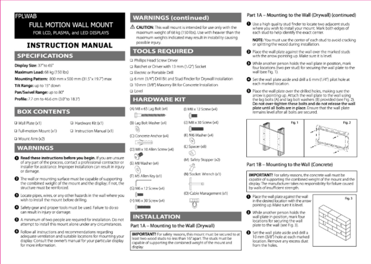
- (A) M8 × 63 Lag Bolt ×4
- (B) Lag Bolt Washer ×4
- (C) Concrete Anchor ×4
- (D) M8 × 10 Allen Screw ×4
- (E) M8 Washer ×4
- (F) M5 Allen Key ×1
- (G) M6 × 12 Screw ×4
- (H) M6 × 30 Screw ×4
- (I) M8 × 12 Screw ×4
- (J) M8 × 30 Screw ×4
- (K) M6 Washer ×4
- (L) Spacer ×8
- (M) Safety Stopper ×2
- (N) Socket Wrench ×1
- (O) Cable Management ×1
Installation Reference Photos
Installation Overview
Part 1A/1B — Mounting the Wall Plate
Drywall: This mount must be secured to at least two wood studs no less than 16" apart, capable of supporting the combined weight of mount and display. Use a stud finder, mark stud centers, hold the wall plate (arrow pointing up) level over the studs, mark 4 bolt locations, drill 6mm (1/4") pilot holes, then attach with lag bolts (A) and washers (B) — do not over-tighten, and keep the plate level.
Concrete: The wall must be capable of supporting the combined weight of mount and display (manufacturer is not responsible for failure due to insufficient wall strength). Position the plate level, mark 4 locations, drill 10mm (3/8") holes, clear dust, insert concrete anchors (C) flush with the surface, then attach the plate with lag bolts (A) and washers (B).
Part 2 — Attaching the Mount to the Wall Plate
Place the mount onto the wall plate right-side up, align the 4 mounting holes (shifting left/right as needed), insert and tighten the M8×10 Allen screws (D) with washers (E) using the M5 Allen key (F) — top pair first, then bottom pair. Attach the cable management piece (O) at the bottom of the mount.
Part 3 — Attaching the Mount Arms to the Display
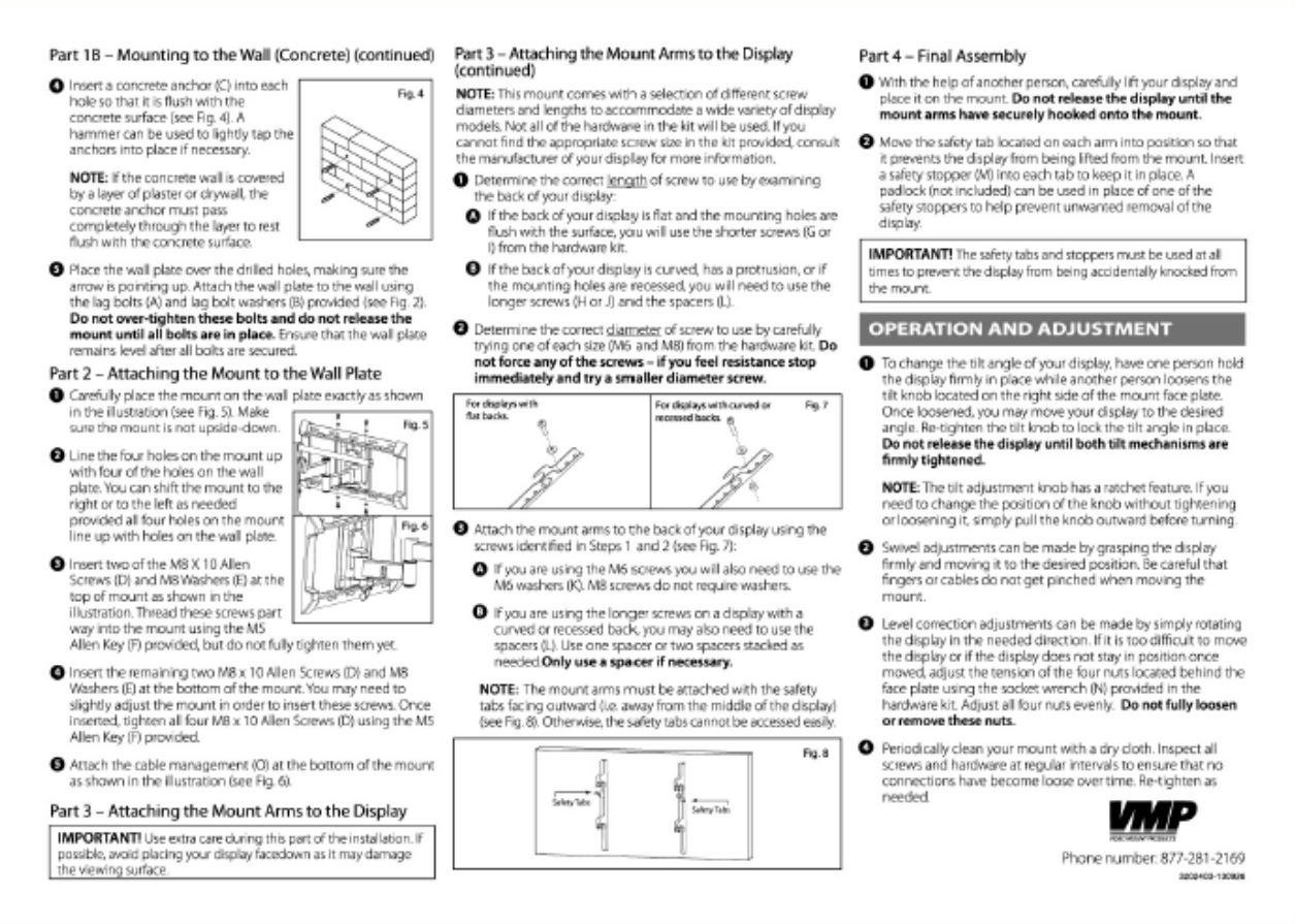
Determine correct screw length by examining the back of the display: flat/flush mounting holes use the shorter screws (G or I); curved, protruding, or recessed mounting holes require the longer screws (H or J) plus spacers (L). Determine correct diameter (M6 or M8) by test-fit — never force a screw; if you feel resistance, try a smaller diameter. Attach the arms with the safety tabs facing outward (away from the display's center) so they remain accessible. Use M6 washers (K) with M6 screws; M8 screws need no washer.
Part 4 — Final Assembly
With a second person's help, lift the display and hook the mount arms onto the mount — do not release the display until both arms are securely hooked. Move each arm's safety tab into position to prevent lift-off, then insert a safety stopper (M) into each tab (a padlock can substitute for one stopper). The safety tabs and stoppers must remain in place at all times.
Operation & Adjustment
- Tilt: With one person holding the display, loosen the tilt knob on the right side of the mount face plate, adjust to the desired angle, then re-tighten before releasing the display. The tilt knob has a ratchet feature — pull it outward to reposition without tightening/loosening.
- Swivel: Grasp the display firmly and move to the desired position, being careful not to pinch fingers or cables.
- Level correction: Rotate the display as needed. If movement is too stiff or the display won't hold position, adjust the tension of the 4 nuts behind the face plate evenly using the socket wrench (N) — do not fully loosen or remove these nuts.
- Maintenance: Periodically clean the mount with a dry cloth and inspect all screws/hardware for looseness, re-tightening as needed.
Manufacturer
Video Mount Products (VMP) — High Value Products. Phone: 877-281-2169. www.videomount.com