
Sensaphone FGD-0007 — Passive Infrared Motion Detector Wiring Instructions
Wiring and mounting instructions for the Sensaphone FGD-0007 Passive Infra-Red Motion Detector.
Full text manual (for reference)
Wiring instructions for the Sensaphone FGD-0007 Passive Infra-Red Motion Detector — used to monitor movement of warm bodies in a monitored area and trigger a dial-out alert when motion is detected.
Overview
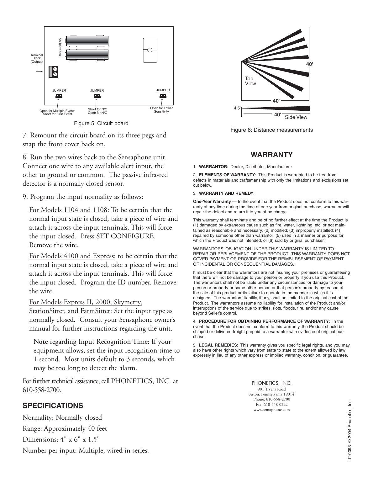
The detector has a range of up to 40 feet directly ahead and approximately 20 feet to either side at 40 feet distance. Recommended mounting height is 4.5 feet. It can be mounted in either a surface wall mount or a corner mount position, with the sensor's window facing left (not up).
Warning: Do not face the sensor toward the sun with the cover off — this will damage the sensor.
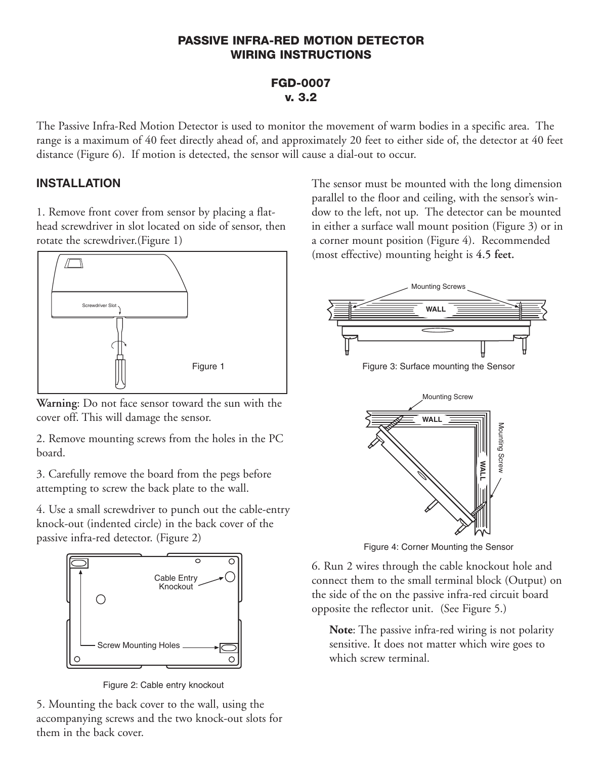
Installation Steps
- Remove the front cover by placing a flat-head screwdriver in the slot on the side of the sensor and rotating it.
- Remove mounting screws from the holes in the PC board.
- Carefully remove the board from the pegs before screwing the back plate to the wall.
- Use a small screwdriver to punch out the cable-entry knockout in the back cover.
- Mount the back cover to the wall using the accompanying screws and the two knockout slots.
- Run 2 wires through the cable knockout hole and connect them to the small terminal block (Output) on the side of the circuit board opposite the reflector unit. Wiring is not polarity sensitive — it does not matter which wire goes to which screw terminal.
- Remount the circuit board on its three pegs and snap the front cover back on.
- Run the two wires back to the Sensaphone unit. Connect one wire to any available alert input, the other to ground or common. The detector is a normally closed sensor.
Programming the Input Normality
- Models 1104 and 1108: Attach a wire across the input terminals to force the input closed, press SET CONFIGURE, then remove the wire.
- Models 4100 and Express: Attach a wire across the input terminals to force the input closed, program the ID number, then remove the wire.
- Models Express II, 2000, Skymetry, StationSitter, FarmSitter: Set the input type as normally closed. Consult your Sensaphone owner's manual for further instructions.
- Input Recognition Time: If your equipment allows, set the input recognition time to 1 second — most units default to 3 seconds, which may be too long to detect the alarm.
Specifications
- Normality: Normally closed
- Range: Approximately 40 feet
- Dimensions: 4" x 6" x 1.5"
- Number per input: Multiple, wired in series
- Power: AA batteries
Warranty
One-Year Warranty: In the event the product does not conform to warranty within one year from original purchase, the warrantor will repair the defect and return the product at no charge. Warranty is void if the product is damaged by extraneous causes, modified, improperly installed, repaired by someone other than the warrantor, used for an unintended purpose, or resold by the original purchaser. Warrantor's obligation is limited to repair or replacement; incidental or consequential damages are not covered.