
RISCO WatchOUT Pole & Conduit Adaptors — Installation Instructions
Installation instructions for the RISCO WatchOUT DT/PIR pole and conduit mounting adaptors.
Full text manual (for reference)
Installation instructions for the RISCO/Rokonet WatchOUT DT/PIR Accessory adaptors — Pole Adaptor (RA300P0000A), Conduit Adaptor (RA300C0000A), and combined Pole + Conduit adaptors — used to mount the WatchOUT detector to a pole or conduit run.
Pole Adaptor Instructions (RA300P0000A)
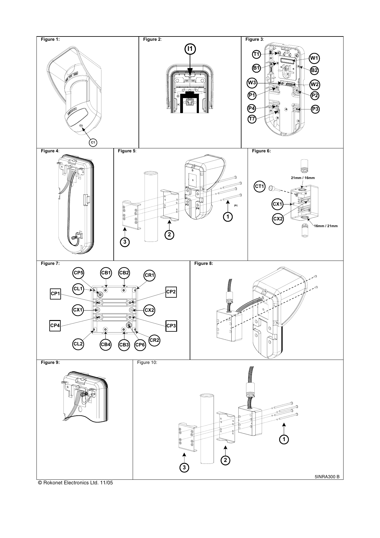
- Open the WatchOUT front cover (unlock C1, Figure 1).
- Release the internal base (unlock I1, Figure 2).
- Open knockouts on the external base (Figure 3): W2/W3 wire entry knockouts, P1-P4 pole connection knockouts, T7 optional back tamper knockout.
- Move the back tamper on the internal base to the lower right side (Figure 4).
- Rest the clamps from both sides of the pole and secure the 4 screws and washers through knockouts P1-P4 and the external holes on the metal bracket (Figure 5).
- Insert external wires through external base W2, W3 (Figure 3).
- Insert external wires and tamper wires through the internal base (Figure 4).
- Secure the internal base to the external base (lock I1, Figure 2).
- Close the front cover (lock C1, Figure 1) and walk test the detector.
Conduit Adaptor Instructions (RA300C0000A)
- Open the WatchOUT front cover (unlock C1, Figure 1).
- Release the internal base (unlock I1, Figure 2).
- Open knockouts on the external base (Figure 3): W1 wire entry knockout, B1/B2 conduit adaptor connection knockouts, T1 tamper knockout (used for wall mounting).
- On the conduit adaptor, remove the cable wiring knockout for the required diameter: 21mm (0.83") or 16mm (0.63") (Figure 6).
- Mount the conduit adaptor:
- Mounting at 45°: Remove the corner wall mounting knockouts on the relevant side (CL1-CL2 or CR1-CR2, Figure 7), connect and secure the conduit adaptor to the wall. Note: 45° installation does not support back tamper protection.
- Wall mounting: Remove wall mounting knockouts CB1-CB4 (Figure 7), connect and secure the conduit adaptor to the wall, then insert the back tamper extension unit on the top-left corner of the conduit adaptor (CT1, Figure 6).
- Insert external wires through external base W1 (Figures 3, 8).
- Secure the external base to the conduit adaptor using the supplied two small screws (Figure 8) from B1-B2 to CX1/CX2 (Figure 7).
- Insert external wires and tamper wires through the internal base (Figure 9).
- Secure the internal base to the external base (lock I1, Figure 2).
- Close the front cover (lock C1, Figure 1) and walk test the detector.
Pole + Conduit Adaptors (Combined)
Step 1 — Attaching the conduit and pole adaptors together
- On the conduit adaptor, remove knockouts: cable wiring knockout for 21mm/16mm diameter (Figure 6), CP1-CP4 pole mounting knockouts, and CP5 or CP6 for the back tamper extension unit (Figure 7).
- Rest the clamps from both sides of the pole and secure the 4 screws and washers through conduit adaptor knockouts CP1-CP4 and the internal holes on the metal clamps (Figure 10).
Step 2 — Attaching the detector to the conduit adaptor
- Open the WatchOUT front cover (unlock C1, Figure 1) and release the internal base (unlock I1, Figure 2).
- On the external base, remove knockouts (Figure 3): W1 wires entry, B1/B2 conduit adaptor connection, T1 back tamper.
- Connect the conduit to the conduit adaptor.
- Insert the back tamper extension unit on the top-left corner of the conduit adaptor (CT1, Figure 6).
- Insert external wires through external base W1 (Figures 3, 8).
- Secure the external base to the conduit adaptor using the supplied two small screws from B1-B2 to CX1/CX2 (Figure 6).
- Insert external wires and tamper wires through the internal base (Figure 9).
- Secure the internal base to the external base (lock I1, Figure 2).
- Close the front cover (lock C1, Figure 1) and walk test the detector.
Manufacturer
© Rokonet Electronics Ltd. (RISCO Group). Drawing reference 5INRA300.