
Qolsys IQ Panel 4 — Installation & Programming Manual
Complete installation and installer/dealer programming reference for the Qolsys IQ Panel 4 all-in-one 7" touchscreen security and smart home panel.
Full text manual (for reference)
Installation reference for the Qolsys IQ Panel 4 — an all-in-one 7" touchscreen security and smart home control panel with built-in camera, dual-band Wi-Fi, PowerG, Z-Wave Plus 700, Bluetooth, and cellular connectivity. Covers physical installation, wiring, power-up, and the full installer/dealer programming menu tree (Software Version 4.0.1).
Overview
The IQ Panel 4 provides full security and smart home functionality in a single interface. This guide covers hardware installation and the menus, features, and settings accessible only with a valid installer/dealer code — not the end-user features (those are covered in a separate IQ Panel 4 User Guide).
Panel Overview
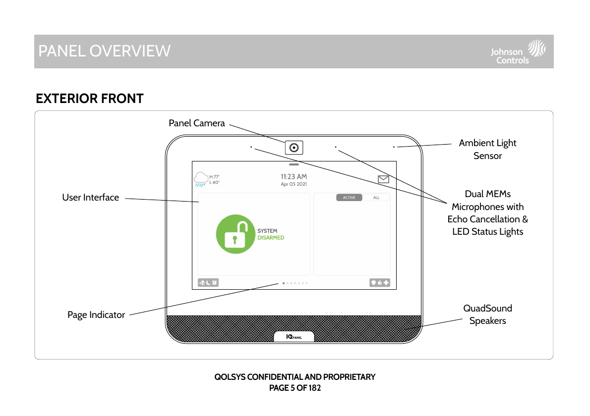
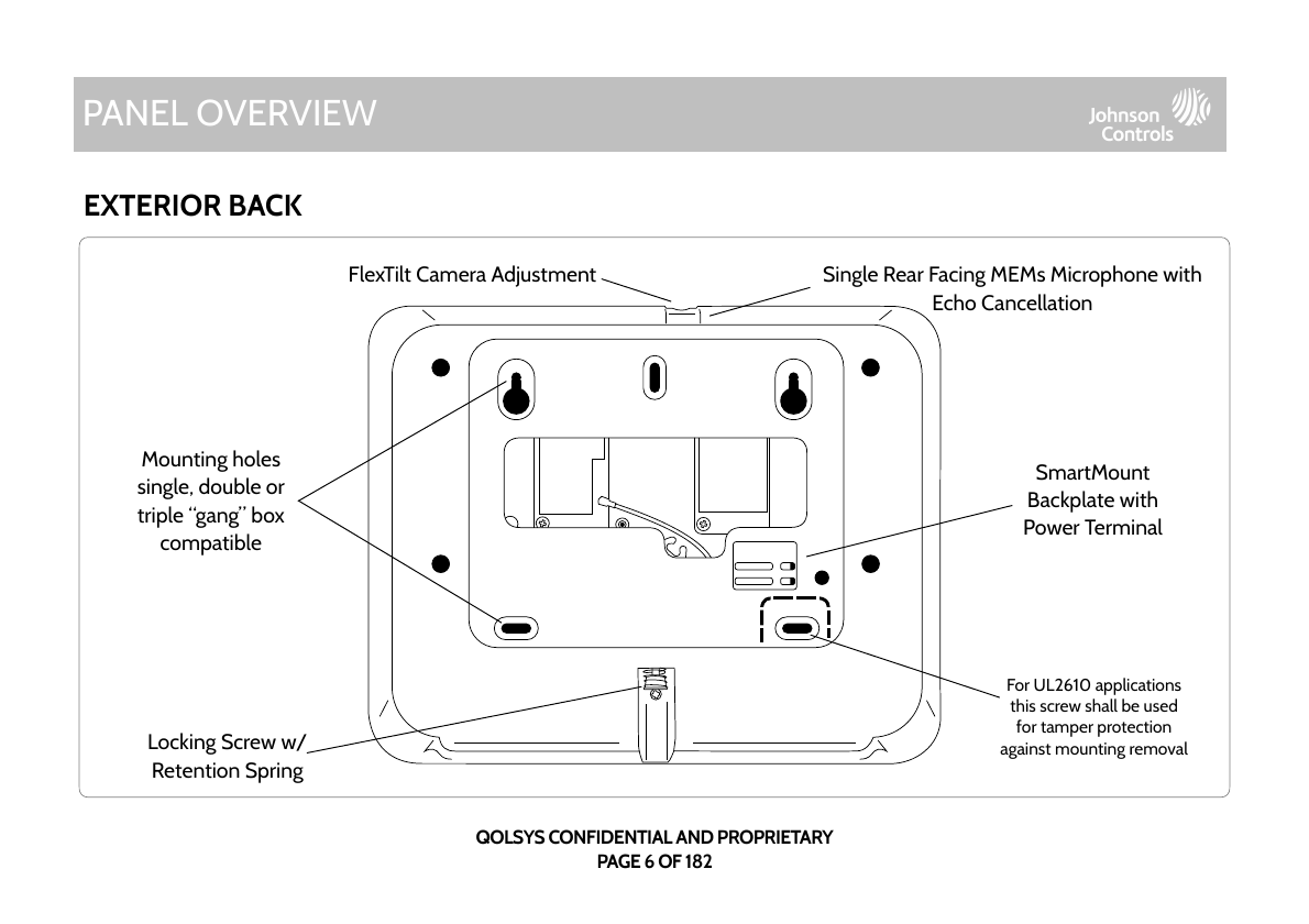
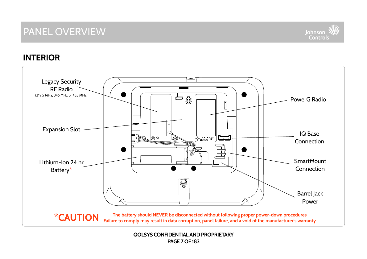
Caution: The battery should NEVER be disconnected without following proper power-down procedures. Failure to comply may result in data corruption, panel failure, and voiding of the manufacturer's warranty.
Installing the Panel
Wall Mount
- Mount the SmartMount backplate to the wall using #6 flat head screws and appropriate wall anchors, ensuring it is level. (For UL/ULC Commercial Burg installations — UL2610/ULC-S304 Security Level II — use only the wall mount option, and a screw is required in the break-away wall tamper for UL 2610.)
- Connect the power supply to the barrel jack on the back of the panel, or to the (+) and (-) terminals on the backplate if using custom length wire.
- Latch the top of the panel onto the SmartMount backplate, swing the panel down toward the backplate, and press firmly against the wall.
- With a small Phillips screwdriver, screw in the locking screw from the bottom of the panel to secure it to the wall.
Table Stand (Optional)
Plug the included power supply's barrel connector into the panel's barrel jack. Locate the SmartMount table stand, insert its hooks into the back of the panel, then swing down and press into place. Route the power wire out the middle slot of the table stand, then secure the panel to the stand with the bottom locking screw.
IQ Base Speaker (Optional)
Connect the IQ Base power cable to the BLACK connector inside the panel (see the Interior diagram above). Insert the top hooks into the back of the panel and press into place, secure with the bottom locking screw, then plug the barrel connector into the barrel jack on the bottom of the IQ Base — ensure it's pushed all the way in.
Wiring Diagram / Power Requirements
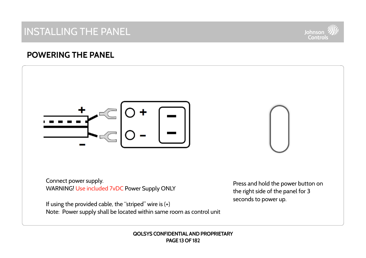
- WARNING: Use 7vDC power supply ONLY.
- Input rating: 100–240vAC, 50/60Hz, 0.2A. Output rating: 7.0vDC, 1.0A or 7.0vDC, 1.5A (Model SW-070100AB or SW-070150A).
- If using custom length wire: 18AWG wire no longer than 98.5 ft to ensure sufficient power at the panel. Minimum permissible wire size is 22 AWG.
- Power supply must be located within the same room as the control unit.
Powering the Panel
Connect the power supply (striped wire is positive if using the provided cable). Press and hold the power button on the right side of the panel for 3 seconds to power up.
FlexTilt Camera Adjustment
Use a small Phillips screwdriver to adjust the FlexTilt screw on top of the panel to angle the built-in camera up or down — helpful when wall-mounting over an existing keypad location or when using the table stand. Turning the screw clockwise angles the camera down; counter-clockwise angles it up. Arm/Disarm the panel to capture a Disarm Photo and test the position, adjusting as needed.
User Interface
The home screen has three sections: the header (date/time, weather, message center, Settings tray), the primary interface (arming options, sensor status, partition select), and the footer (panic options and additional pages).
The Settings tray (swipe down from the top bar) gives quick access to system, battery, Wi-Fi, Bluetooth and cellular status, volume control, brightness, and a lock/status icon. When partitions or screen lock are enabled, a Lock Screen icon appears (touch to switch partitions); when disabled, a Status icon appears (touch to return to the security page).
Programming (Installer/Dealer Menus)
Screen Lock & Setup Wizard
When "Screen Lock" or "Partitions" is enabled, a lock screen (4- or 6-digit) appears when the panel wakes. The "Easy Install Wizard" is a step-by-step onscreen programming tool for consistent installs. Access it via Settings → Advanced Settings → enter Dealer (2222), Installer (1111), or Master (1234) code → Setup Wizard.
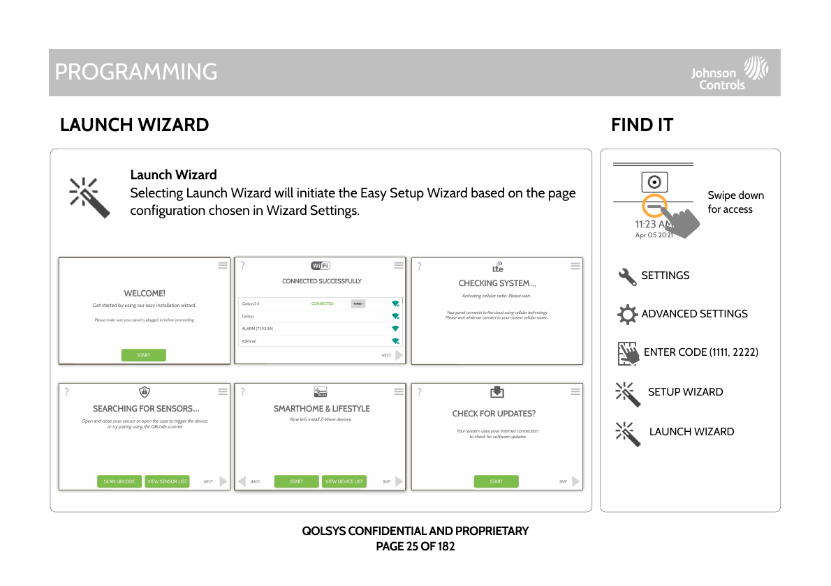
Wizard Settings let you choose which pages appear during the walkthrough: Update, Security (with Advanced/PRO or Simple/DIY sensor pairing), Panel Glass Break, Z-Wave, Bluetooth, Users, Dealer contact info, IQ Remote, Sensor Signal Test, and Download Mobile App — all enabled by default.
Settings Menu (No Code Required)
| Setting | Description |
|---|---|
| Display | Adjust brightness, font size, 12/24 hour time |
| Weather Temperature | Toggle Fahrenheit / Celsius |
| Status | View current status of security sensors (Zone, Name, Open/Close/Active/Idle/Tamper/Failure, Battery, History) and alarms |
| Z-Wave Device Status | View Z-Wave device Name, Type, Status (Normal/Failure), Battery, Alerts, History |
| Other Z-Wave Devices | Z-Wave devices learned into the panel but not part of the main UI (lights, locks, thermostats, garage doors) |
| Automation | Add/edit/manage local lighting automation rules (separate from Alarm.com cloud rules) — e.g. Night, Evening, Front Door, Doorbell triggers |
| Activity Monitor | Disarm 24-hour sensor groups (8, 9, 25) with a valid code — Quick Access (300 sec) or full Deactivate |
| Advanced Settings | Access installer/dealer programming — requires Dealer (2222), Installer (1111), or Master (1234) code |
| Smart Energy Optimizer | Shift thermostat energy usage to off-peak hours |
Sensors, Wi-Fi, Z-Wave, Bluetooth Devices
Advanced Settings covers adding/editing/deleting Security Sensors (with Auto Learn or QR-code scan, partition assignment, sensor type/group/name, chime type, voice prompts), Wi-Fi Devices (access point settings, connected device list, IQ Remote pairing, 3rd-party connections), Z-Wave Devices (add/clear/delete, view/edit associations, SmartStart, provisioning list), and Bluetooth Devices (add/edit/delete for disarm and audio streaming).
System Tests & Diagnostics
Built-in diagnostics include Wi-Fi Test, Sensor Test, Cellular Test, Z-Wave Test, Rediscover Network, Neighbor Info, Counters, Z-Wave Diagnostics (basic and advanced), PowerG Test, Zigbee Test, Panel Glass Break Test, Dual Path Test, Daughter Cards Test, and overall Panel Test.
Customization
User Management, Dealer Branding, Contact Info, On-Screen Branding, Wi-Fi connection setup, Weather widget, and Photo Frame mode are all configurable from the installer menu tree.
Maintenance
Software Upgrade: Check for and download updates over Wi-Fi, or upload via the panel's own Access Point mode; automatic background checks run periodically.
Battery Replacement: Follow proper power-down procedure before disconnecting the battery to avoid data corruption or panel failure. This device and its lithium battery must be recycled/disposed of per applicable US and Canadian regulations — do not discard with general household waste.
Power Down / Reboot: Panel Reboot performs a standard restart; Hard Reboot is used when the panel is unresponsive. Power Down safely shuts the unit off before servicing or battery removal.
Specifications
| Item | Spec |
|---|---|
| Platform | Android 9 |
| Display | 7" LCD, 1280×800, 300 cd/m², 24-bit (16.9M colors) |
| Processor | Qualcomm Snapdragon 8-core SOM, 16GB NAND Flash |
| Touchscreen | Capacitive glass, multi-touch |
| User Codes | Up to 242, role-based (Dealer, Installer, Master, User, Guest, Duress) |
| Wi-Fi | 802.11 a/b/g/n/ac dual-band 2.4/5GHz, built-in router capability |
| Cellular | LTE CAT4 (Bands 2/25, 4/66, 5/26, 7, 12/17, 13, 14 non-First Net) |
| Z-Wave Plus 700 | Up to 137 devices (80 lights, 20 locks, 10 thermostats, 21 misc, 6 garage doors) |
| PowerG | Up to 128 devices, 915MHz long-range encrypted two-way wireless |
| Security RF | S-Line encrypted 319.5MHz, 345MHz, or 433MHz depending on model |
| Bluetooth | BLE 4.2 (disarming, audio streaming) |
| Camera | 8MP wide-angle, 120° FOV, fixed focus with FlexTilt adjustment |
| Microphones | 3× MEMs with echo cancellation |
| Speakers/Siren | QuadSound 4× 4W front-facing speakers, 85dB siren |
| Battery | Lithium-Ion 3000mAh, 18650 type |
| Dimensions | 6.1"H × 7.5"W × 1"D (155 × 191 × 26mm) |
| Power Supply | 7vDC 1000mA CC or 7vDC 1.5A CC; Input 100-240VAC 50/60Hz (UL/cUL evaluated at 120vAC) |
| Certification | UL985, UL1023, UL2610, ULC-S545, ULC-S304 (UL/cUL/ULC Residential Fire & Burglary, Commercial Burglary) |
| Operating Temperature | 0 to 49°C, up to 93% RH, indoor dry ordinary locations only. Storage: -20 to 50°C |
Supported Sensors
The IQ Panel 4 supports several wireless sensor protocols depending on the model radio installed:
- 319 MHz S-Line: IQ Door/Window-S (QS1133/1135/1136/1137-840), IQ Motion-S (QS1230/1231-840), IQ Glass-S (QS1431-840), IQ Smoke (QS5110-840), IQ CO (QS5210-840), Keyfobs (QS1331-840), Tilt Sensor (QS1131-840), Flood Detector (QS5536-840), Temperature Sensor (QS5535-840), IQ Hardwire 16-F (QS7133-840).
- 345 MHz: Door/Window (5816WMWHUL, 5815UL), Motion (5800PIR-COM, 5898, 5800PIR), Glass Break (5853UL), Smoke (5806W3, 5808W3), Smoke/CO Combo (5800COMBO), CO (5800CO, GG-CO8345/2GIG-CO8-345).
- 433 MHz DSC: Door/Window (WS4945NA), Motion (WS4904P, WLS914-433), Glass Break (WLS912L-433), Shock (EV-DW4927SS), Smoke (WS4936), CO (WS4933), 2/4-Button Keyfobs (WS4949/WS4939), Pendant (WS4938), Repeater (WS4920).
- 433 MHz AT&T Digital Life: Door/Window (SW-ATT-V2/RDW), PIR Motion (SW-ATT-PIR), Glassbreak (SW-ATT-GB), Smoke (SW-ATT-SMKT), CO (SW-ATT-CO), Keyfob (SW-ATT-FOB), Repeater (SW-ATT-RPTR4), Hardwire Translator (SW-ATT-TAKRF).
- PowerG: Door/Window (PG9945/9307/9309/9312), Shock (PG9935), Dual-Tech Motion (PG9984), Glassbreak (PG9922), Heat (PG9936H), Keyfobs (PG9929/9939/9949/9938), Outdoor Motion (PG9902/9974/9994), PIR Motion (PG9904/9914/9924/9862/9872), PIR with Camera (PG9934/9944), Sirens (PG9901/9911), Smoke (PG9936), CO (PG9933), Repeater (PG9920), Vanishing Contact (PG9303/9975), Wired-to-Wireless Converter (PG9WLSHW8).
SKUs Covered
This manual applies to IQ Panel 4 models across three carrier variants: Verizon (IQP4001–IQP4003, incl. BLK), AT&T (IQP4004–IQP4006, incl. BLK), and Telus (IQP4007–IQP4009, incl. BLK). Conforms to UL Std. S985, 1023 & 2610; certified to ULC Sub C1023 & ULC Std S545.
Manufacturer
Qolsys, Inc. Technical support: techsupport@qolsys.com. Document#: IQP4-IM-NA, Version 1.1.A.1.