
Optex INS-QXI-ST InSight Visual Verification PIR Camera — Installation Instructions
Installation instructions for the Optex INS-QXI-ST InSight Series Visual Verification PIR Camera, designed for integration with the CHeKT alarm verification platform.
Full text manual (for reference)
Installation instructions for the Optex INS-QXI-ST InSight Series Visual Verification PIR Camera — a combination PIR motion detector and camera designed for integration with the CHeKT alarm verification platform.
Before Installation
Warnings & Cautions
- Do not destroy, disassemble, or modify the unit.
- Avoid intentional watering.
- Mounting height: 2.2m (7'3") to 2.7m (8'11").
- Do not mount on an unstable wall; avoid excessive tilt.
Parts Identification
PIR detector, PIR cover, camera unit, camera angle adjusting screw, bracket angle adjusting screw, mounting plate, back cover.
Accessories Included
4x20mm mounting screws, T20 Torx wrench, PIR area masking strips, waterproof cap for LAN connection.
Step 1 — Installation
- Remove the mounting plate from the main body.
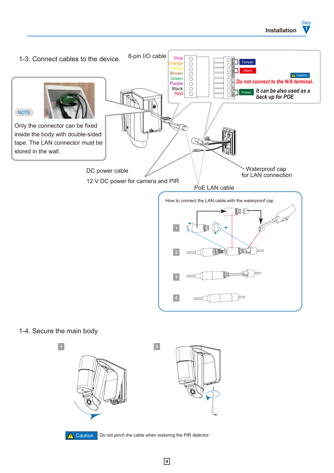
- Install the mounting plate to the wall using 2 screws. Hook the fall-prevention wire. To pass cables through the wall, drill a 25mm (1") or larger hole; use a single-gang box for exposed wiring.
- Connect cables to the device — see the wiring diagram below for the 8-pin I/O cable color coding, plus the DC power cable (12V DC for camera and PIR, can double as PoE backup) and PoE LAN cable with waterproof cap.
- Secure the main body back onto the mounting plate. Caution: do not pinch the cable when restoring the PIR detector.
Step 2 — IP Address Settings
The default InSight network type is dynamic (DHCP). If a DHCP server is present, the address is set automatically. Otherwise, after one minute the camera sets a static default:
- Initial address: see the label on the InSight unit
- Username: root
- Default password: OPTEX (change as appropriate)
Download the IP installer tool and refer to the full InSight Camera manual online for detailed IP configuration.
Step 3 — Device Registration to CHeKT Portal
- Go to the CHeKT Dealer Portal to log in (request a dealer account from CHeKT support if you don't have one).
- Select the Customer from the dashboard.
- Select the Site Devices tab.
- Select the bridge device to associate with the sensor camera.
- Access bridge settings via the gear icon.
- Select the appropriate tab to register the PIR camera.
Step 4 — Camera Angle & PIR Area Settings
These adjustments are optional — check the defaults first and only proceed if changes are needed.
4-1. Horizontal Adjustment
Remove the back cover (raise it up, then pull back). Horizontal PIR area direction adjusts ±95°. Only one side needs to be loosened to adjust.
4-2. Vertical Adjustment
Vertical PIR area adjustment ranges 0° to -20°. Caution: only use the vertical angle adjustment to make the detection surface parallel to the ground's inclination — not for general aiming.
Camera Angle Adjustment
Loosen the screws to slide the camera vertically. Range: 20° minimum to 35° maximum, with a 30° default.
4-3. PIR/VCA Settings
Refer to the InSight VCA manual for detailed PIR and VCA (video content analytics) area configuration. If the camera's vertical angle is adjusted, this section's settings must be matched for optimal sensor performance.
4-4. PIR Area Masking
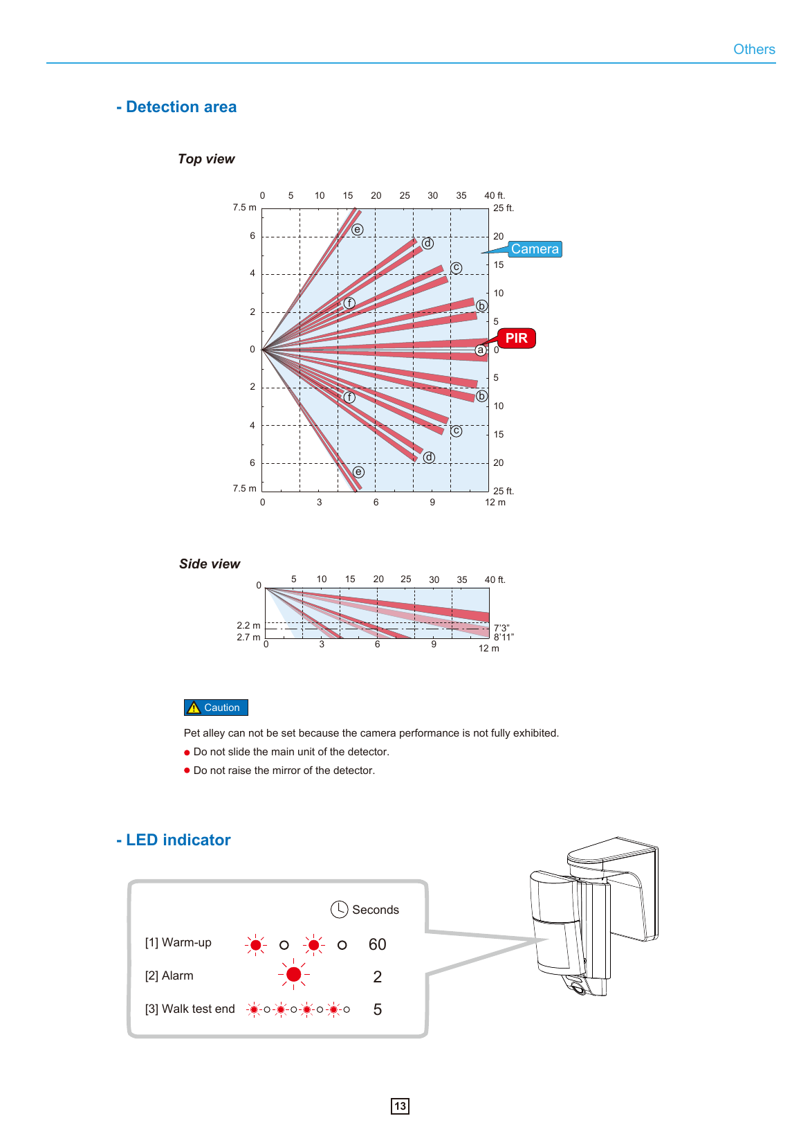
Default detection area is 12.0m (40') at 120° wide. If no masking is needed, skip this step. To mask: unlock the PIR cover with a flathead screwdriver, lift it up, then attach the area masking strips over the zones (labeled a–f) you want to exclude from detection.
4-5. Switch Settings (DIP Switches 1–4)
- PIR Sensitivity: Low / Middle (default) / High / Super High, set via switches 3 & 4
- Alarm Output: N.O./N.C. — do not change; must be kept to N.C. (N.O. setting may cause unstable performance)
- LED: ON (default) or OFF
- Switches 5–8 are reserved for future use
Caution: Do not move the mirror or PCB from factory settings, or "Pet Alley" mode cannot be configured.
4-6. Reassemble
Put the back cover on after completing all adjustments.
Step 5 — Checking
5-1. Walk Test
- Turn the LED back ON if it was turned off (DIP switch 1, default ON).
- Close the PIR cover.
- Walk around the detection area to confirm it's set as intended (walk at least 1.0m/3'3" away from the detector).
- Turn LED off again if desired for the final installation.
- Fix the PIR cover with the included lock screw when complete.
After the cover is reinstalled, the LED lights up according to the alarm output for 3 minutes to confirm operation. Conduct a walk test at least once a year.
5-2. System Check
Check the detection image on the CHeKT monitoring portal to confirm end-to-end verification is working.
Specifications
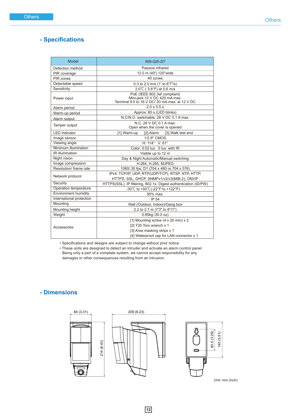
| Model | INS-QXI-ST |
| Detection Method | Passive infrared |
| PIR Coverage | 12.0m (40') at 120° wide, 40 zones |
| Detectable Speed | 0.3 to 2.0 m/s (1' to 6'7"/s) |
| Sensitivity | 2.0°C (3.6°F) at 0.6 m/s |
| Power Input | PoE (IEEE 802.3af); Mini-jack 12V DC 420mA max; Terminal 9.5–16V DC / 20mA max at 12V DC |
| Alarm Period | 2.0 ± 0.5s |
| Warm-up Period | ~60s (LED blinks) |
| Alarm Output | N.C./N.O. switchable, 28V DC 0.1A max |
| Tamper Output | N.C. 28V DC 0.1A max; opens when cover is opened |
| Image Sensor | 1/2.8" CMOS |
| Viewing Angle | H: 114° / V: 61° |
| Minimum Illumination | Color: 0.02 lux, 0 lux with IR |
| IR Illumination | Visible up to 12m |
| Night Vision | Day & Night, automatic/manual switching |
| Image Compression | H.264, H.265, MJPEG |
| Resolution / Frame Rate | 1080p/30fps, D1 (704x480 or 704x576) |
| Network Protocol | IPv4: TCP/IP, UDP, RTP, RTSP, NTP, HTTP, HTTPS, SSL, DHCP, SNMPv1/v2/v3 (MIB-2), ONVIF |
| Security | HTTPS (SSL), IP filtering, 802.1x, Digest authentication (ID/PW) |
| Operation Temperature | -30°C to +50°C (-22°F to +122°F) |
| Environment Humidity | 95% max |
| International Protection | IP54 |
| Mounting | Wall (outdoor/indoor) or gang box; height 2.2–2.7m (7'3"–8'11") |
| Weight | 0.85kg (30.0 oz) |
Dimensions
Detection Area
Compliance & Privacy Notice
This product produces moving images of a designated area but does not store or register such images itself. The installer/user is responsible for confirming compliance with local laws regarding personal information, privacy protection, portrait rights, and any required signage/notification — OPTEX is not liable for disputes between the user and third parties regarding image use.
FCC: Tested and found compliant with Class A digital device limits per FCC Rules Part 15. Operation in a residential area is likely to cause harmful interference, in which case correction is at the user's expense.
Factory Reset
To reset (e.g., forgotten password): locate the factory reset switch on the cable, and press for 5 seconds. This resets the IP address, ID, password, and all camera settings to defaults. Caution: do not pinch the cable when restoring the PIR detector.
Manufacturer
OPTEX CO., LTD. (Japan) — www.optex.net
OPTEX INC. / Americas HQ (U.S.) — www.optexamerica.com