
NAPCO FireWolf FW-2S — Photoelectric Smoke Detector Installation Instructions
Installation instructions for the NAPCO FireWolf FW-2S Advanced Photoelectric Smoke Detector, covering wiring diagrams, NFPA 72 placement guidance, testing, and compatible control panels.
Full text manual (for reference)
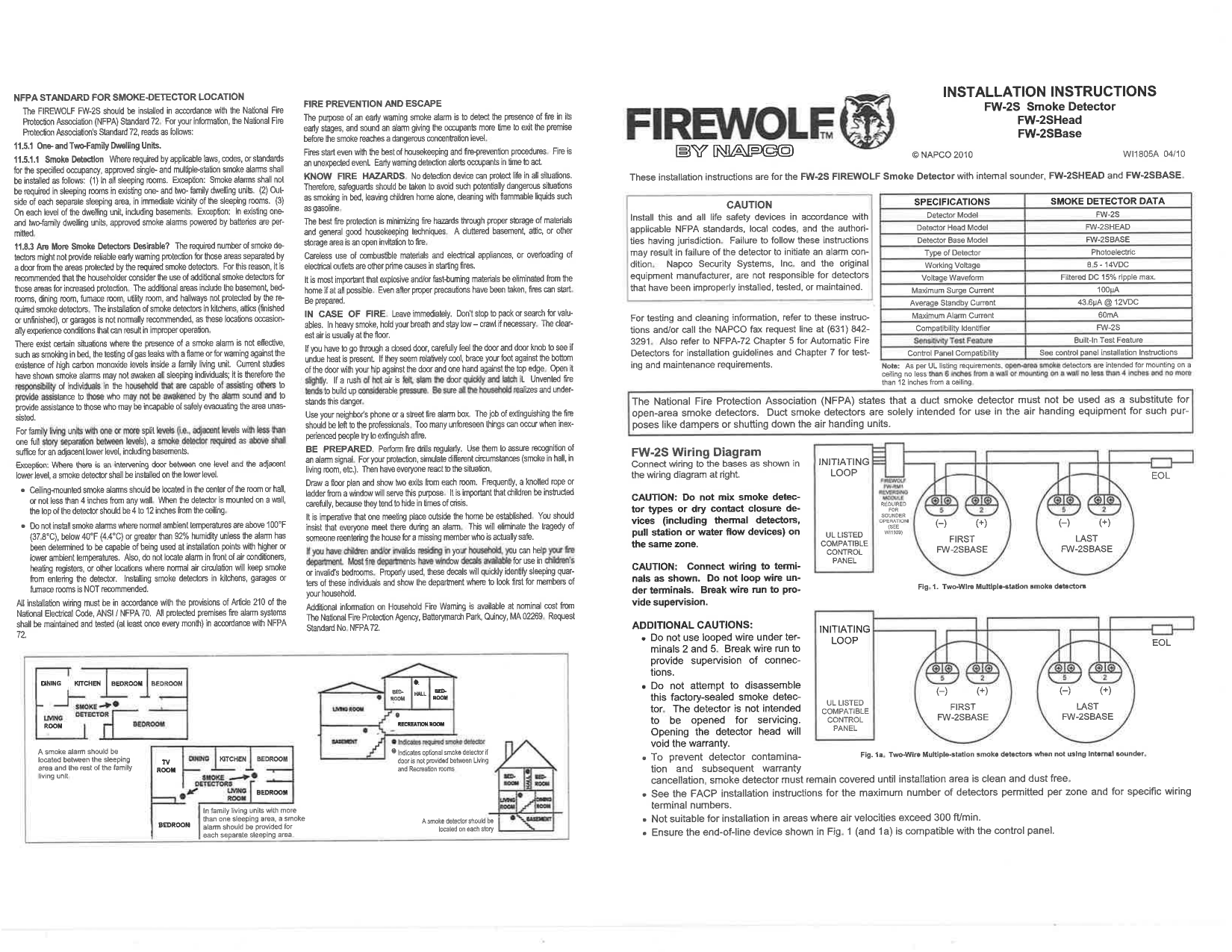
Quick reference for the NAPCO FireWolf FW-2S Advanced Photoelectric Smoke Detector (includes the FW-2SHead detector head and FW-2SBase mounting base). This manual is diagram-heavy; the images below plus the full downloadable PDF cover the wiring diagrams and installation photos in detail.
Specifications
| Detector Model | FW-2S |
| Type | Photoelectric |
| Working Voltage | 8.5–14 VDC |
| Voltage Waveform | Filtered DC, 15% ripple max |
| Max Surge Current | 100µA |
| Average Standby Current | 43.6µA @ 12VDC |
| Max Alarm Current | 60mA |
| Sensitivity Test Feature | Built-in |
Safety Warnings
- Must be installed per NFPA/local codes; improper installation voids manufacturer responsibility.
- Do not mix detector types on the same zone.
- Do not loop wire under terminals 2 (+) and 5 (−).
- Not suitable where air velocity exceeds 300 ft/min.
- Duct smoke detectors serve a different purpose than open-area smoke detectors — do not substitute one for the other.
- Unit is factory-sealed; opening it voids the warranty.
Installation Overview
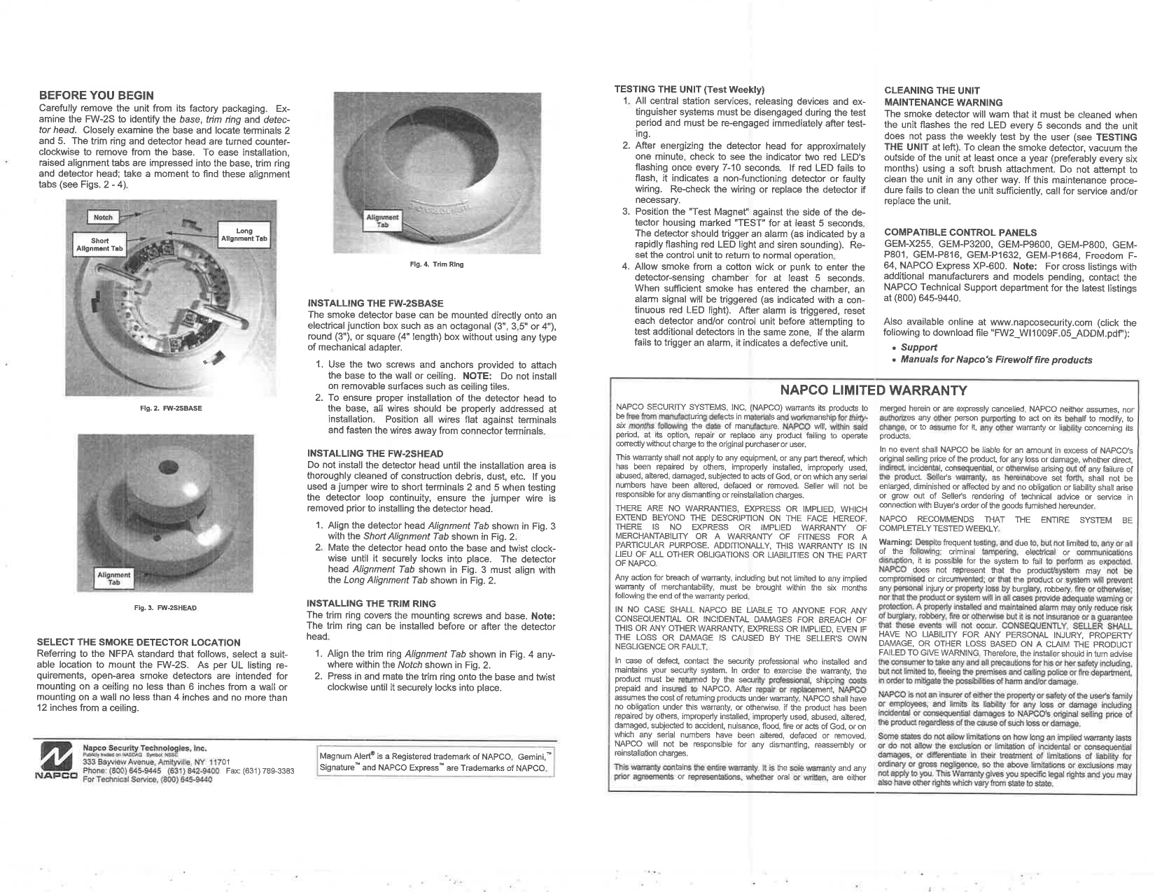
- Unpack and identify the base, trim ring, and detector head; note the alignment tabs.
- Install the FW-2SBASE by mounting it to a junction box (octagonal, round, or square) and wiring the terminals.
- Install the FW-2SHEAD by aligning the tabs and twist-locking it into place.
- Install the trim ring.
- Choose detector location per NFPA guidance: on the ceiling, 6" from any wall; on a wall, 4–12" from the ceiling.
Weekly Testing Procedure
- Use the Test Magnet to trigger the built-in sensitivity test feature.
- Monitor the LED for the correct flash pattern.
- Perform a smoke test using a cotton wick (per manufacturer instructions).
- Confirm the alarm signal reaches the control panel, then reset.
Maintenance
Vacuum the exterior of the detector every 6 months. Do not disassemble the unit.
Compatible Control Panels
GEM-X255, GEM-P3200, GEM-P9600, GEM-P800, GEM-P801, GEM-P816, GEM-P1632, GEM-P1664, Freedom F-64, NAPCO Express XP-600.
Warranty
36-month NAPCO Limited Warranty. See full documentation for exclusions and liability limitations.
Napco Security Technologies, Inc., 333 Bayview Ave, Amityville, NY 11701. Tel: (800) 645-9445. Document #: WI1805A 04/10, © NAPCO 2010.