
Home Automation 23A00-1 — Surface Remote Temperature Sensor Installation Guide
Installation instructions for the Home Automation Model 23A00-1 Surface Remote Temperature Sensor — a retrofit accessory for RC-Series Omnistat thermostats.
Full text manual (for reference)
Installation instructions for the Home Automation Model 23A00-1 Surface Remote Temperature Sensor — a retrofit accessory that adds remote-location temperature sensing to an existing RC-Series Omnistat thermostat.
Description
The Model 23A00-1 is a surface-mount temperature sensor that installs on an existing RC-Series Omnistat, allowing the thermostat to monitor temperature from a remote location. This lets the thermostat (or group of thermostats) be located somewhere else entirely, without a visible thermostat in the monitored area.
Specifications
Dimensions: 2"W x 1.5"H x 1"D
Installation Steps
- Install the Omnistat base in the selected thermostat location and connect it to the heating/cooling equipment per the manufacturer's instructions. Connect the thermostat to the base and confirm normal operation.
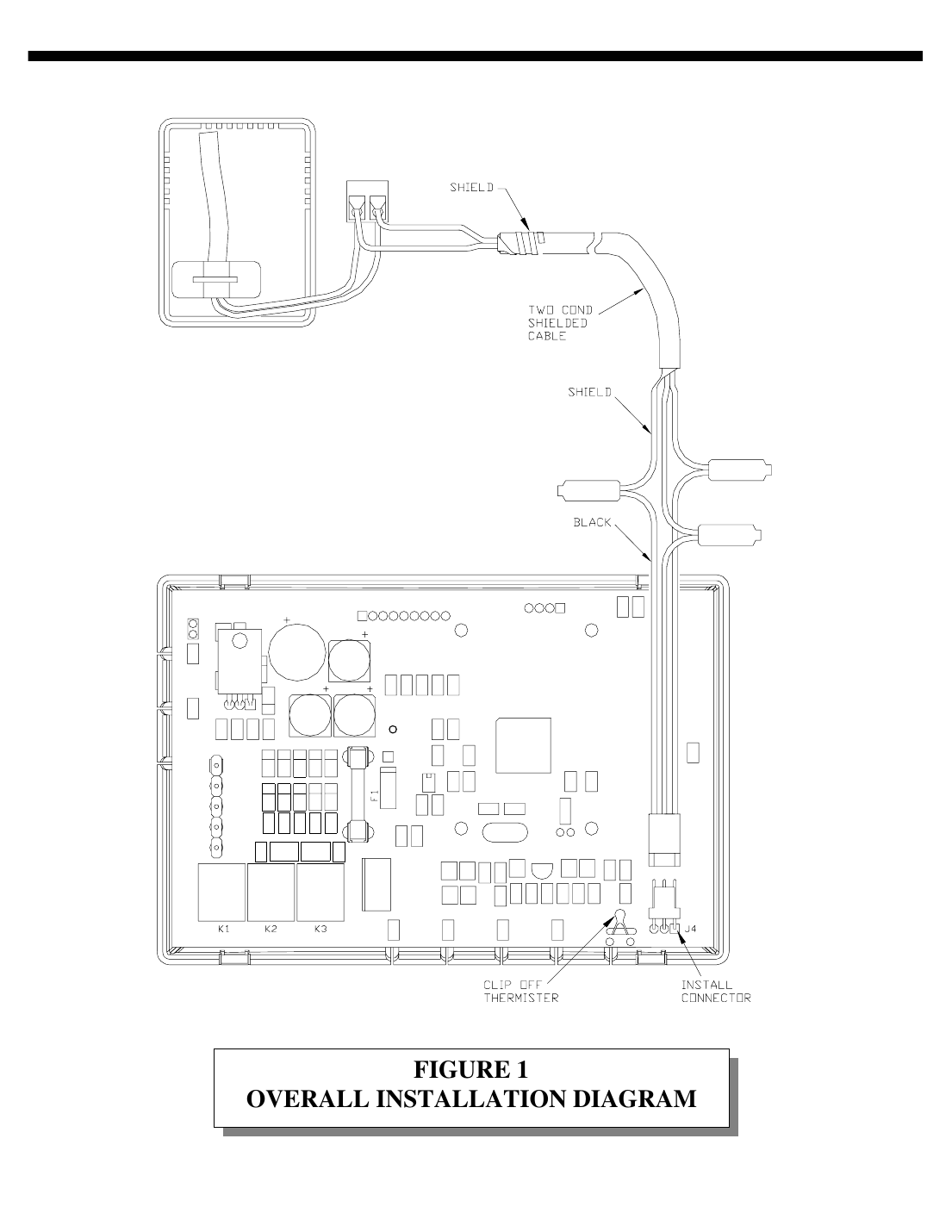
- Disconnect the thermostat from the base. Locate the 3 solder holes on the lower right side of the thermostat PCA, marked J4.
- Using a clean soldering iron and safety glasses, carefully solder the supplied connector to the soldering holes.
- Run a twisted-pair, shielded cable from the Omnistat to the Remote Temperature Sensor location:
- Up to 100 ft: typical twisted-pair, PVC-insulated, shielded cable.
- 100–150 ft: twisted-pair with polypropylene-insulated conductors, shielded.
- 150–250 ft: twisted-pair with foam-polyethylene-insulated conductors, shielded.
- Wire runs must not exceed 250 feet.
- Open the cover of the Model 23A00-1 sensor. Connect the data wires of the shielded cable to the terminal block on the temperature sensor.
- Wrap the shield around the cable jacket and tape it in place.
- At the Omnistat location, connect the black conductor of the supplied cable to the shield using the supplied wire splices. Connect the green conductors to the data wires using the supplied wire splices.
- Carefully clip off the existing thermistor (temperature-sensing device) from the thermostat using wire cutters (see diagram).
- Connect the supplied cable to the installed connector (J4) on the Omnistat.
- Reconnect the thermostat to the base and confirm it displays the proper temperature.
Overall Installation Diagram
Manufacturer
Home Automation, Inc., 5725 Powell Street, Suite A, New Orleans, LA 70123. Phone: 504-736-9810. Fax: 504-736-9890.