
FortrezZ DE Series Electric Actuator — Installation, Maintenance & Operational Manual
Installation, maintenance, and operational manual for the FortrezZ DE Series electric actuator, used to power valve and damper open/close operation.
Full text manual (for reference)
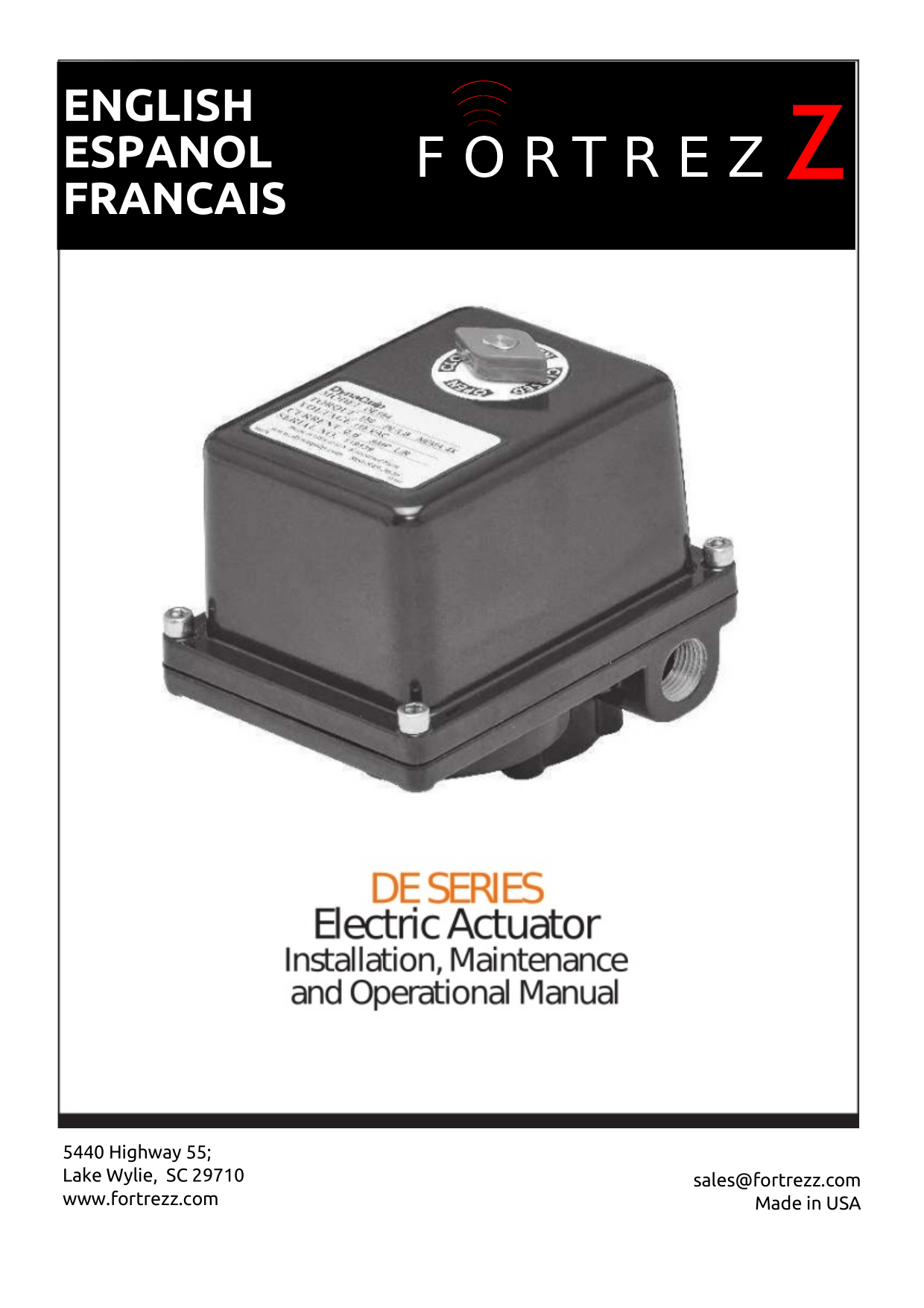
Overview
The FortrezZ DE Series Electric Actuator is used to power open/close valves and dampers. Actuators can be mounted in any position and wired in parallel (not series). The output shaft rotates clockwise to close and counterclockwise to open, uses a Type 316 stainless steel output shaft, and includes thermo overload protection to guard the motor against overheating.
Safety Warnings
- Do not apply electric power unless the unit is fully assembled and mounted.
- Always disconnect the electric power source and relieve system pressure prior to maintenance. Eye protection is recommended while servicing.
- Failure to comply with these warnings could result in personal injury and/or product damage.
- Do not manually operate AC or DC voltage units with power connected.
Inspection Upon Receipt
- Visually inspect for shipping damage.
- Verify the Model Number matches your order.
- Verify the electrical supply voltage matches the actuator label.
- Verify the NEMA rating is as required (Weatherproof/Corrosion Resistant: NEMA 4, 4X).
- Check that the mounting bolt pattern and output shaft/adapter configuration match your application.
Installation
- Before mounting, verify the valve torque requirement is less than the actuator's rated output torque. Manually operate the valve/damper to ensure ease of opening and closing.
- Check the output shaft adapter fits the valve/damper stem before inserting into the actuator.
- Confirm the actuator's open/closed position matches the equipment it will be mounted to.
- Mount to the top plate of the valve, valve bracket, or damper, ensuring the actuator base sits flush with the top plate.
- Tighten mounting bolts using a cross pattern, drawing them down evenly.
Electrical Installation
Caution: Make sure power is off at the main supply source before wiring.
Verify the electrical supply voltage matches the required actuator voltage. Connect power to the terminal block per the schematic wiring diagram inside the actuator cover. Power to terminals 1 and 2 rotates the shaft counterclockwise (open); power to terminals 1 and 3 rotates it clockwise (close). Actuators can be wired in parallel — wiring in series can cause erratic cycling.
- Turn on power to the actuator.
- Operate to close position (power to terminals 1 and 3, CW rotation) and check alignment.
- Operate to open position (power to terminals 1 and 2, CCW rotation) and check alignment.
- If alignment is needed, remove power and follow the cam alignment procedure below.
Setting Cams for Alignment
Setting Open Position
If the valve did not open completely: turn power off, remove the cover, loosen the set screw in the top cam and rotate it clockwise. Manually rotate the shaft counterclockwise to the desired open position, then slowly rotate the cam counterclockwise until the switch lever opens (you should hear a light click). To verify with a multimeter: set to Resistance/Continuity mode, connect leads to terminals 2 and 4, and rotate the cam counterclockwise until continuity is achieved. Tighten the set screw to lock the open position. If the valve travels too far past open, manually rotate the shaft clockwise past open and repeat this procedure.
Setting Close Position
If the valve did not close completely: turn power off, remove the cover, loosen the set screw in the bottom cam and rotate it counterclockwise. Manually rotate the shaft clockwise to the desired close position, then slowly rotate the cam clockwise until the switch lever opens (light click). Verify with a multimeter on terminals 3 and 5. Tighten the set screw to lock the close position. If the valve closes too far, manually rotate the shaft counterclockwise past close and repeat this procedure.
Restore power, operate the unit several times, and recheck positions. Repeat cam alignment if needed, then replace the cover.
Wiring Diagrams
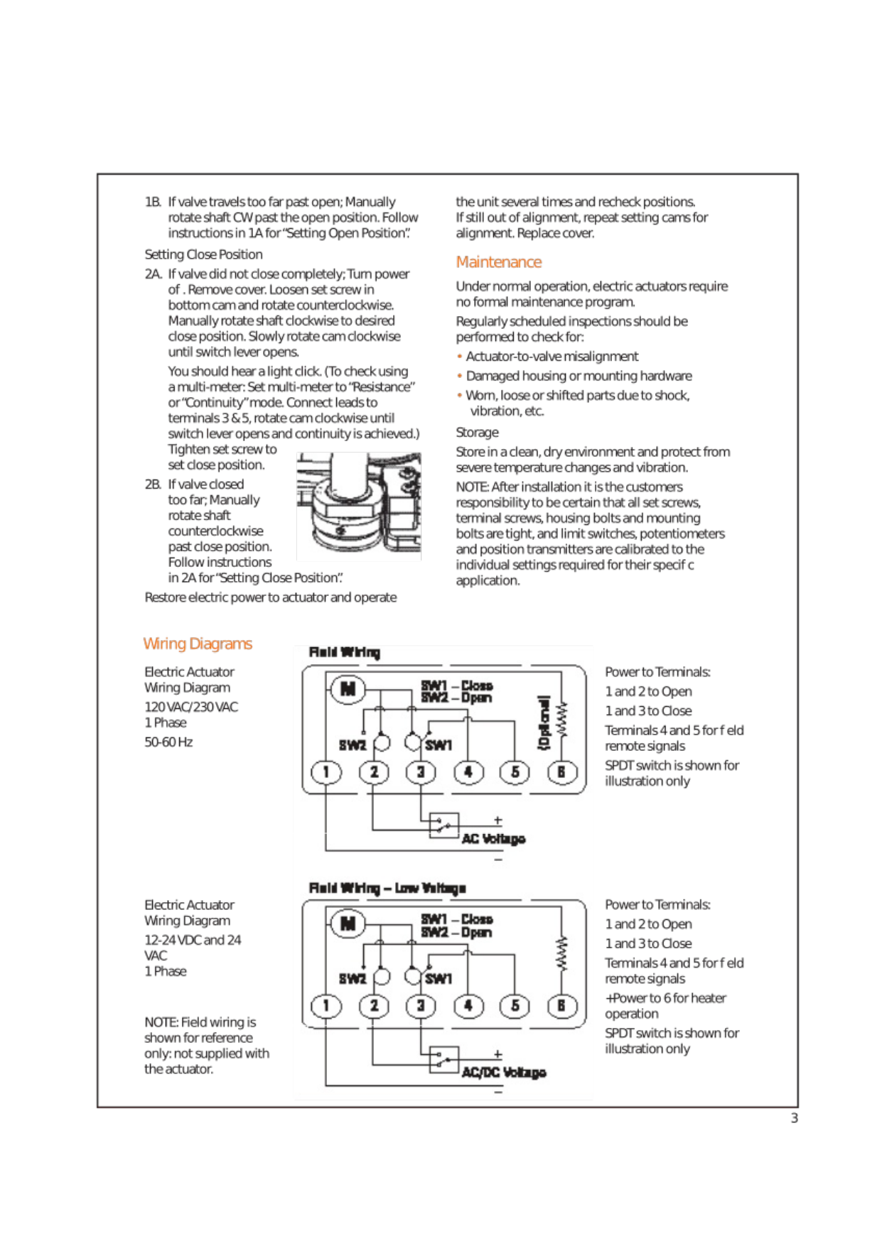
Power to terminals 1 and 2 = Open; power to terminals 1 and 3 = Close. Terminals 4 and 5 are for field remote signals. On the low-voltage diagram, +power to terminal 6 enables heater operation. SPDT switch shown for illustration only.
Maintenance & Storage
Under normal operation, electric actuators require no formal maintenance program. Regularly scheduled inspections should check for actuator-to-valve misalignment, damaged housing or mounting hardware, and worn/loose/shifted parts due to shock or vibration. Store in a clean, dry environment protected from severe temperature changes and vibration.
Note: After installation, it's the customer's responsibility to ensure all set screws, terminal screws, housing bolts, and mounting bolts are tight, and that limit switches, potentiometers, and position transmitters are calibrated to the individual settings required for the application.
Troubleshooting
| Problem | Cause / Corrective Action |
|---|---|
| Power to unit but no operation | Check for broken/loose wires, blown fuses, or tripped breakers; check limit switch positions; check for motor burnout (verify correct voltage per wiring diagrams); check the valve for proper operation. |
| Erratic actuator performance | Check ambient temperature — the motor's thermal cut-out switch may shut it down if overheated; this actuator has a 50% duty rating (max 30 min run time per hour); check for low voltage "brown out"; check for motor stall from a foreign obstruction or increased torque load. |
| Low torque output | Check that power supply is within listed specifications; check for overheating (see above). |
| Incorrect travel or operation | Refer to "Setting Cams for Alignment" above; inspect and correct/replace any malfunctioning control device (relay, switch, etc.) if the circuit isn't energized for the full cycle duration. |
Safety First / Record Keeping
After inspecting the actuator, record for future reference: Actuator Model Number, Output Torque, Voltage, Serial Number, Date of Installation, Location, and Valve/Line Tag Number.
Manufacturer
FortrezZ, LLC — 5440 Highway 55, Lake Wylie, SC 29710 · www.fortrezz.com · sales@fortrezz.com · Made in USA