
Enbrighten In-Wall Smart Dimmer (58438 / ZWA3016) — Quick Start Guide
Quick Start Guide for the Enbrighten In-Wall Smart Dimmer, models 58438 / ZWA3016 — a Z-Wave Plus certified wireless lighting control dimmer.
Full text manual (for reference)
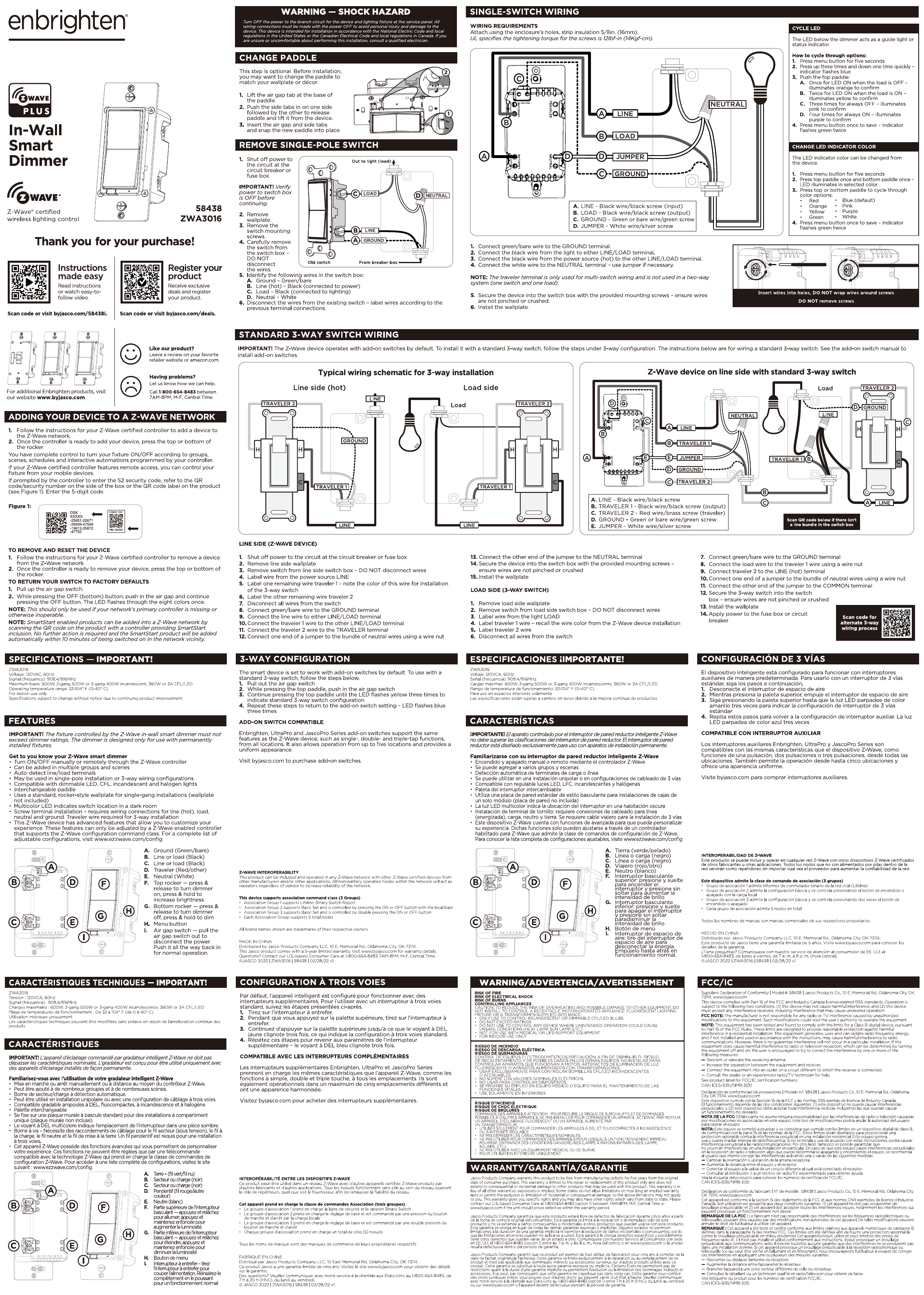
Quick Start Guide for the Enbrighten In-Wall Smart Dimmer, Models 58438 / ZWA3016 — a Z-Wave Plus certified wireless lighting control dimmer switch. This guide is highly illustrated; see the full downloadable PDF for the complete wiring diagrams. This page covers the safety essentials, wiring overview, and Z-Wave setup for quick reference.
Shock Hazard Warning
Turn OFF power at the breaker/fuse box before installation. Wiring diagrams inside the guide reference GROUND, LINE, LOAD, NEUTRAL, and TRAVELER connections. Terminal screw tightening torque: 20 in-lb (2.26 N·m). The fixture controlled by this dimmer must not exceed the dimmer's load ratings, and it's designed only for use with permanently installed fixtures.
Adding the Device to a Z-Wave Network
- If the device was previously used on another network, follow your Z-Wave certified controller's instructions to remove it from that network first.
- Follow your controller's instructions to add the device to your Z-Wave network.
- SmartStart-enabled products can be added by scanning the QR code on the product packaging with a compatible controller/app — no manual inclusion steps needed.
To return the device to factory defaults: pull the air gap switch, then rapidly press the power/ON-OFF button the specified number of times per the device's reset sequence (see diagram). The Enbrighten light will indicate when the reset completes.
Single-Pole Wiring Overview
- Turn off power at the breaker before removing the old switch.
- Remove the switch plate and mounting screws; carefully pull the old switch from the wall box, leaving wires connected.
- Identify and label the Ground, Line, Load, and Neutral wires per the wiring diagram before disconnecting.
- Connect the bare/green wire to the GROUND terminal.
- Connect the black wire from the power source to the LINE terminal.
- Connect the black wire to the load (fixture) to the LOAD terminal.
- Connect the white wire to the NEUTRAL terminal.
- Carefully fit the device into the wall box without crushing or overcrowding the wires, then attach the wallplate.
Wire color legend: LINE — black, traced; LOAD — black, untraced; GROUND — green or bare; NEUTRAL — white.
Standard 3-Way Switch Wiring
The Z-Wave device is designed to replace one switch in a 3-way circuit while pairing with a standard mechanical 3-way switch on the other end. Follow the 3-way-specific wiring diagram (see image above) rather than the single-pole diagram.
Line side (Z-Wave device):
- Shut off power to the circuit at the breaker.
- Remove the old switch and label the Line, Ground, and Traveler wires.
- Connect the ground wire to the GROUND terminal.
- Connect the line (hot) wire to the LINE terminal.
- Connect the traveler wires to the TRAVELER terminals.
- Connect the jumper wire to the bundle of traveler wires as shown in the diagram.
Load side (standard 3-way switch):
- Remove the load-side wallplate and old switch.
- Label the traveler and ground wires.
- Connect the ground wire.
- Connect the traveler wires to the switch terminals.
- Secure the switch back into the wall box.
Wire color legend: LINE — black, traced; TRAVELER 1 — black, untraced; TRAVELER 2 — red; GROUND — green or bare; JUMPER — white.
For 4-way or more-way applications, this switch is compatible with add-on Enbrighten/GE/Jasco switches, which extend Z-Wave signaling to additional switch locations.
Changing the LED Indicator Color
Press the Menu button repeatedly to cycle through available LED indicator colors: Blue, Green, Red, Purple, Orange, Yellow, Pink, and White. Hold the Menu button to save the selected color.
Replacing the Paddle
- Turn off power at the breaker.
- Lift the paddle off at the top edge.
- Pull the side tabs in to release, then remove the old paddle.
- Insert the new paddle, aligning the top and side tabs.
- Snap the paddle into the side slots until it clicks into place.
FCC Statement
This device complies with Part 15 of the FCC Rules. Operation is subject to two conditions: (1) this device must not cause harmful interference, and (2) this device must accept any interference received, including interference that may cause undesired operation. Changes or modifications not expressly approved could void the user's authority to operate the equipment.
Manufacturer: Enbrighten. Customer support: 1-800-604-6608. Also available in Spanish and French per the full guide. Doc: 240-61104N-10Y 58438 QSG v1.