
Cool Components HiFlo Vent Basic System (VS-HFB) — Installation Instructions
Installation instructions for the Cool Components HiFlo Vent Basic System (VS-HFB), a fan-driven cabinet/closet ventilation system, including mounting diagrams and polarity reference.
Full text manual (for reference)
Installation instructions for the Cool Components HiFlo Vent Basic System (VS-HFB) — a fan-driven cabinet/closet ventilation system designed to more aggressively vent equipment enclosures and reduce heat buildup.
Overview
The HiFlo Vent Basic System is designed to aggressively vent cabinets, closets, or entire rooms. For venting rooms or closets, consider the full HiFlo System (which includes two grills and a temperature controller) unless you're venting through a door or surface where only one side needs a grill — those items can also be purchased separately.
Installation Planning
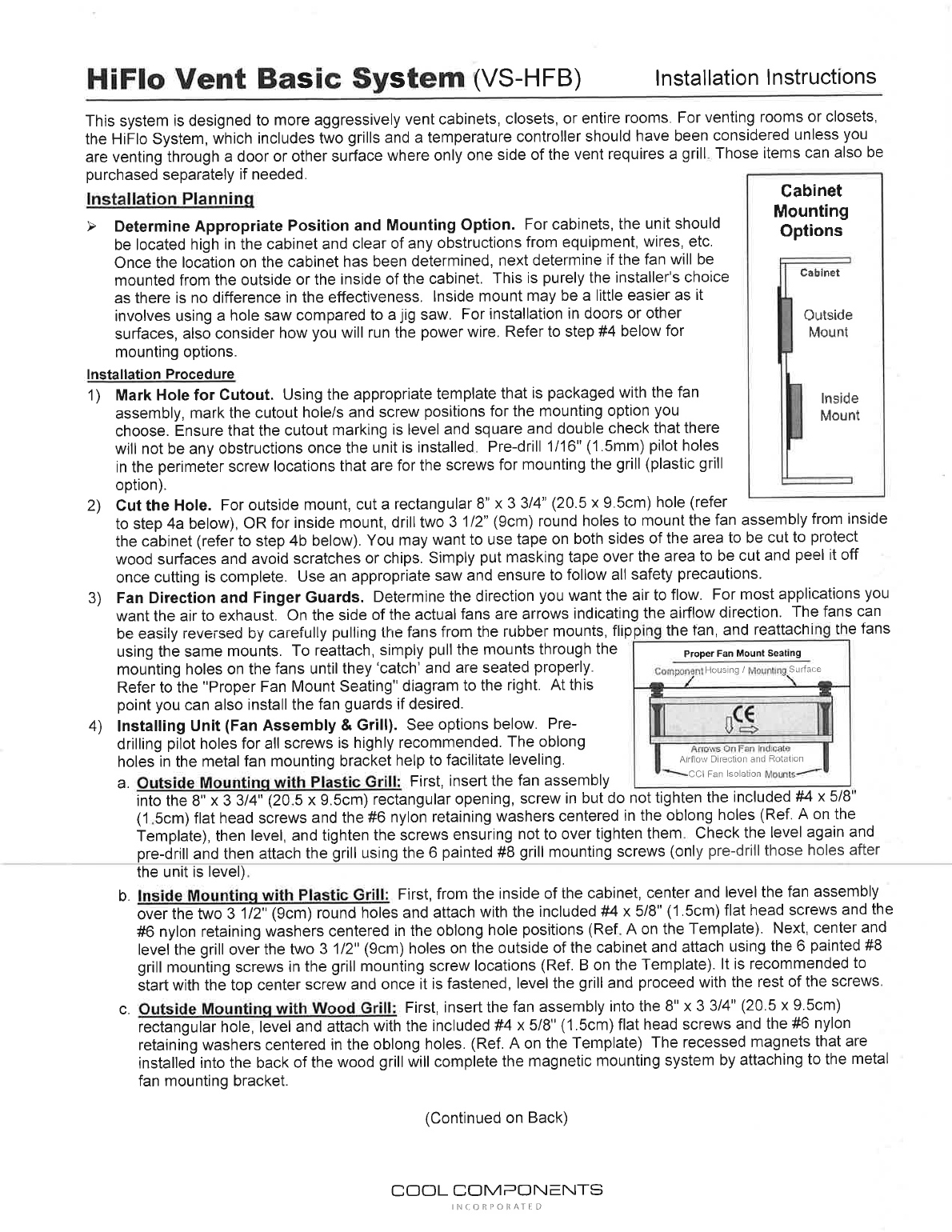
Determine the appropriate position and mounting option before cutting anything. For cabinets, mount the unit high in the cabinet, clear of any equipment or wires. Decide whether the fan will mount from outside or inside the cabinet — this is purely installer preference; outside mount uses a hole saw, inside mount uses a jig saw. For door or surface installs, also plan how the power wire will run.
Installation Procedure
- Mark the hole for cutout. Using the template packaged with the fan assembly, mark the cutout hole(s) and screw positions for your chosen mounting option. Ensure the marking is level and square, and double-check for obstructions. Pre-drill 1/16" (1.5mm) pilot holes at the perimeter screw locations for the grill screws.
- Cut the hole. For outside mount, cut a rectangular 8" x 3¾" (20.5 x 9.5cm) hole. For inside mount, drill two 3½" (9cm) round holes. Use tape on both sides of the cut area to protect the surface from scratches/chips.
- Set fan direction and finger guards. Determine desired airflow direction (usually exhaust) — arrows on the side of each fan indicate direction. Fans can be reversed by carefully pulling them from the rubber isolation mounts, flipping, and reattaching (pull the mounts through the fan's mounting holes until they "catch" and seat properly). Install fan guards if desired.
-
Install the fan assembly and grill (pre-drilling pilot holes for all screws is recommended; oblong holes in the metal mounting bracket help with leveling):
- Outside mounting, plastic grill: Insert the fan assembly into the 8" x 3¾" opening, loosely screw in the included #4 x 5/8" flat head screws and #6 nylon retaining washers (centered in the oblong holes), level, then tighten. Re-check level, then pre-drill and attach the grill with the 6 painted #8 grill mounting screws.
- Inside mounting, plastic grill: From inside the cabinet, center and level the fan assembly over the two 3½" round holes and attach with the #4 x 5/8" screws and #6 nylon washers. Then center and level the grill on the outside over the same holes and attach with the 6 painted #8 grill screws — start with the top center screw, level, then finish the rest.
- Outside mounting, wood grill: Insert the fan assembly into the 8" x 3¾" hole, level, and attach with the #4 x 5/8" screws and #6 nylon washers. The wood grill's recessed magnets attach magnetically to the metal fan mounting bracket.
- Inside mounting, wood grill: From inside the cabinet, center and level the fan assembly over the two 3½" round holes and attach with the #4 x 5/8" screws and #6 nylon washers. Attach the #8 washers to the outside using the #4 x 3/8" screws included with the grill package — the wood grill's recessed magnets align to these washers to complete the mount.
- Run the power wire. Route the wire away from obstructions for a clean installation, using appropriate wire management for door/surface mounts.
- Connect power wires. Before plugging in, connect the fan assembly's power wire to the power supply and check for obstructions around the fans. Align the tip with the "+" marking on the connectors — see polarity diagram below.
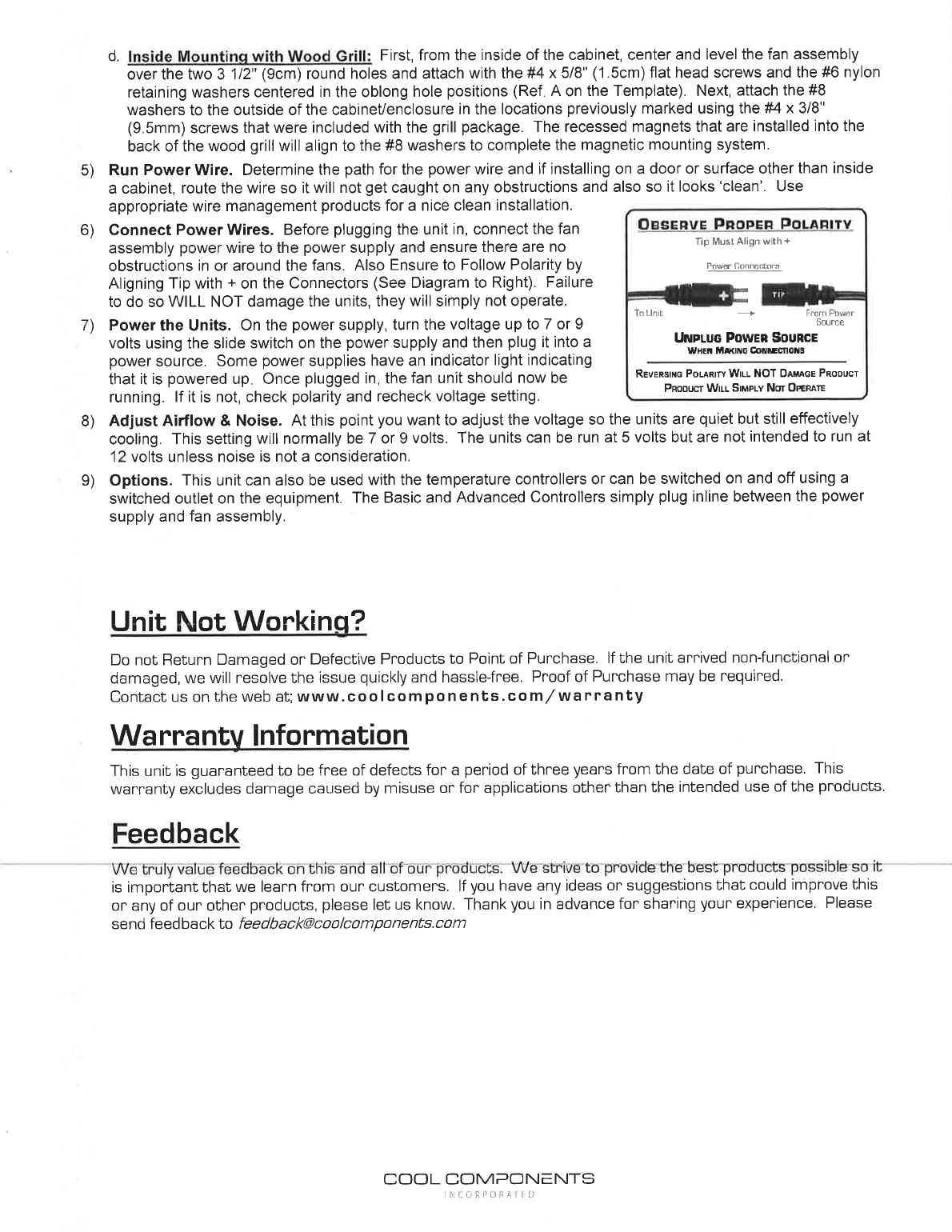
- Power the unit. On the power supply, set the slide switch to 7 or 9 volts, then plug into a power source. The fan should start running. If not, recheck polarity and voltage.
- Adjust airflow & noise. Adjust voltage so the units run quietly while still cooling effectively — typically 7 or 9 volts. Units can run at 5 volts, but are not intended for 12 volts unless noise isn't a concern.
- Optional temperature controllers. This unit can be used with the Basic or Advanced temperature/system controllers (which plug inline between the power supply and fan assembly), or simply switched via a switched outlet.
Unit Not Working?
Do not return damaged or defective products to the point of purchase. Contact Cool Components directly at www.coolcomponents.com/warranty for quick, hassle-free resolution. Proof of purchase may be required.
Warranty
Guaranteed free of defects for 3 years from the date of purchase. This warranty excludes damage from misuse or use outside the product's intended application.
Feedback
Cool Components welcomes feedback and suggestions for product improvement — send to feedback@coolcomponents.com.