
Chief TS218SU — Medium Dual Swing Arm TV Mount Installation Instructions
Installation instructions for the Chief TS218SU medium dual swing arm TV wall mount — weight/structure requirements, VESA bracket configuration, and adjustments.
Full text manual (for reference)
Installation instructions for the Chief TS218SU — a Medium Dual Swing Arm TV mount with pan, tilt, height, and roll adjustment. This page summarizes the safety-critical weight/structure warnings, dimensions, hardware, and adjustment procedures; the full downloadable PDF includes every step and diagram for both wood-stud and concrete/block wall installation.
Critical Safety Warnings
- Weight capacity: The combined weight of the display and all attached components must not exceed 75 lbs (34 kg). Exceeding this can cause the mount to collapse, resulting in injury or equipment damage.
- Structural strength: The wall structure the mount attaches to must be able to support 5 times the combined weight of all equipment. Reinforce the structure before installing if needed.
- Drywall: Maximum drywall thickness at the attachment point is 5/8" (1.6cm). Never install drywall anchors into the seam between drywall pieces.
- Wall type: Designed for 8" concrete, 8"x8"x16" concrete block, clay brick, or 2"x4" wood studs (16" on-center) — not for other wall types without appropriate hardware.
- Never install into cracked, chipped, or flaking concrete — this can lead to serious injury or product damage.
- Not for outdoor use. Never operate a damaged mount — return it to a service center for inspection.
- Use only for its intended purpose; do not use attachments not recommended by the manufacturer.
Dimensions & Motion Range
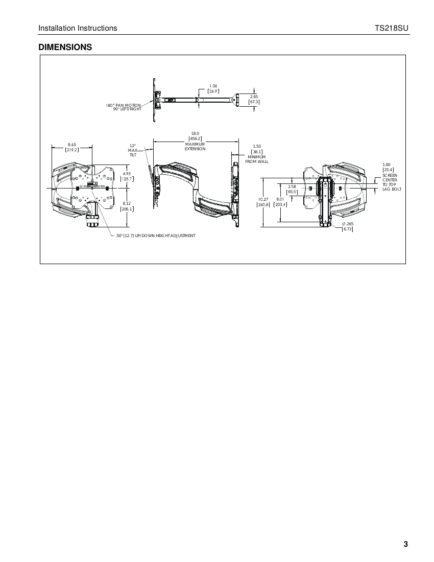
Tools Required
- 1/8" drill bit (wood studs) or 8mm drill bit (concrete)
- 7/16" (11.1mm) drill bit
- #2 Phillips screwdriver
- 5/32" hex key, 3/16" hex key, 1/8" hex key
- Level
Wall Installation
Wood Studs
- Determine mounting location; measure 1" above the desired display center line and mark a hole at the center of a wood stud.
- Drill a 1/8" hole at the marked location.
- Install a 1/4 x 2-1/2" lag bolt, leaving it hanging out 1/2" from the wall, then hang the main assembly onto it via the key-shaped hole.
- Mark, drill (1/8"), and secure the two lower mounting holes with additional lag bolts. Tighten all three lag bolts fully.
Concrete Block, Poured Concrete, or Clay Brick
- Mark the mounting location 1" above the desired center line; drill an 8mm hole and install a concrete anchor.
- Install a lag bolt into the anchor (leave 1/2" protruding), hang the main assembly, then mark the two lower hole locations.
- Remove the assembly, drill two more 8mm holes, install concrete anchors, rehang the assembly, and secure with lag bolts. Tighten all bolts fully.
Display Installation
The faceplate mounts directly to displays with 100x100mm, 200x100mm, or 200x200mm VESA hole patterns (no interface brackets needed). For other patterns (300x300 up to 400x400mm), install interface brackets ("P" and "Q") to the faceplate first, matching the configuration chart to your VESA pattern and orientation (portrait/landscape).
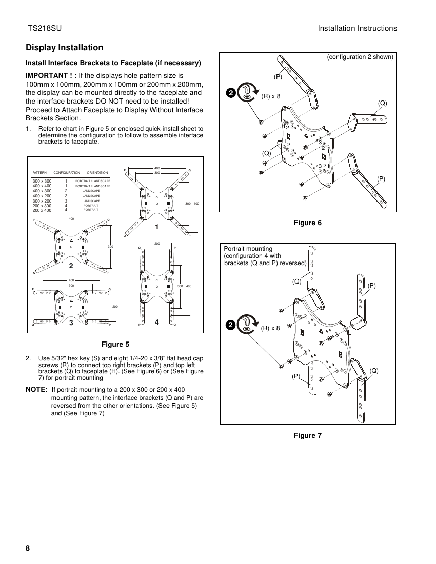
- Screw diameter: Select from 4mm, 5mm, 6mm, or 8mm hardware sets (A-D) based on the display's mounting holes.
- Spacers: Use spacers only if mounting holes are recessed or protrusions prevent the bracket/faceplate from sitting flat against the display.
- Screw length: Use the shortest screw that still protrudes above the washer by a distance equal to or greater than the screw diameter — too short risks poor thread engagement, too long risks contacting internal display components.
- Hang the faceplate onto the main assembly's pitch bracket (teardrop grooves), then secure with two flange nuts and roll flange spacers — don't overtighten if manual roll adjustment is desired later.
Adjustments (Post-Installation)
| Adjustment | How |
|---|---|
| Height | ±1/2" up/down. Remove display, remove top/bottom covers, loosen 4 height adjustment screws with a 1/8" hex key, reposition, retighten, replace covers/display. |
| Roll | Loosen the two flange nuts, rotate display to desired roll position, retighten. |
| Tilt friction | Adjust the tilt friction screws (side of mount) to increase/decrease resistance. |
| Arm tension | Use a 3/16" hex key at any of the three tension adjustment points (two on swing arms, one at the wall plate). |
Cable Management
- Connect all cables to the display first.
- Open the cable management covers on the upper and lower swing arms (unhinge center tabs).
- Route cables along the top of the upper arm and under the lower swing arm; optionally secure with cable ties (not included) through the arm's cable-tie holes.
- Close both cable management covers.
Wall covers: Handle with care during installation/removal — they are fragile and can crack under excessive force.