
Chief FUSION MSA1U/MTA1U/LSA1U/LTA1U — Flat Panel Mount Installation Instructions
Installation instructions for the Chief FUSION Medium and Large Flat Panel Wall Mounts (MSA1U, MTA1U, LSA1U, LTA1U).
Full text manual (for reference)
Installation instructions for the Chief FUSION Medium and Large Flat Panel Wall Mounts — models MSA1U, MTA1U (medium fixed/tilt) and LSA1U, LTA1U (large fixed/tilt). This quick-reference page covers the essential safety warnings, mounting overview, and hardware; refer to the full downloadable PDF for every diagrammed step.
Critical Safety Warnings
- Never operate this mounting system if it is damaged. Return it to a service center for examination and repair. Do not use outdoors.
- Improper installation can lead to the mount falling, causing severe personal injury or damage to equipment. The installer is responsible for ensuring the wall structure can support 5x the combined weight of all mounted components — reinforce the structure as needed before installing.
- Exceeding weight capacity is dangerous. Combined weight of all components on MSA1U/MTA1U must not exceed 125 lbs (56.7 kg); LSA1U/LTA1U must not exceed 200 lbs (90.7 kg).
- If M4 fasteners are used to attach brackets to the screen back (LSA1U/LTA1U only), screen weight may not exceed 150 lbs (68.0 kg).
- Use only for its intended purpose, with attachments recommended by the manufacturer.
- Using screws of improper size can damage the display — properly sized screws thread completely into the display's mounting holes; use longer screws of the same diameter if spacers are required.
- Never place both interface brackets on one side of the wall mount's center line — this is a critical, easy-to-miss error.
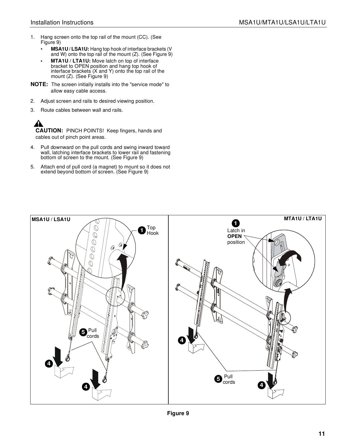
- Watch for pinch points — keep fingers, hands, and cables clear when latching the screen onto the mount.
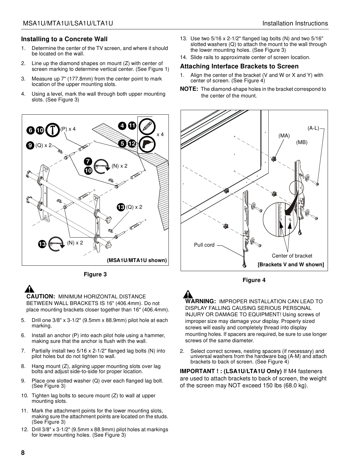
- Minimum horizontal distance between wall brackets is 16" (406.4mm).
Mounting Surface Requirements
These mounts are designed for:
- A bare 8" concrete or 8"x8"x16" concrete block wall, or
- A 2"x4" wood stud wall covered by drywall (max 5/8" thickness) — studs must be 16" on center for MSA1U/MTA1U, or 16"/24" on center for LSA1U/LTA1U
The MTA1U and LTA1U feature tilt brackets (tilts from -2° to 12°, lockable at 0°, 6°, or 12°); the MSA1U and LSA1U use static brackets that hold the TV upright.
Installation Overview
Full illustrated, numbered steps (with hardware call-outs) are in the downloadable PDF. High-level sequence:
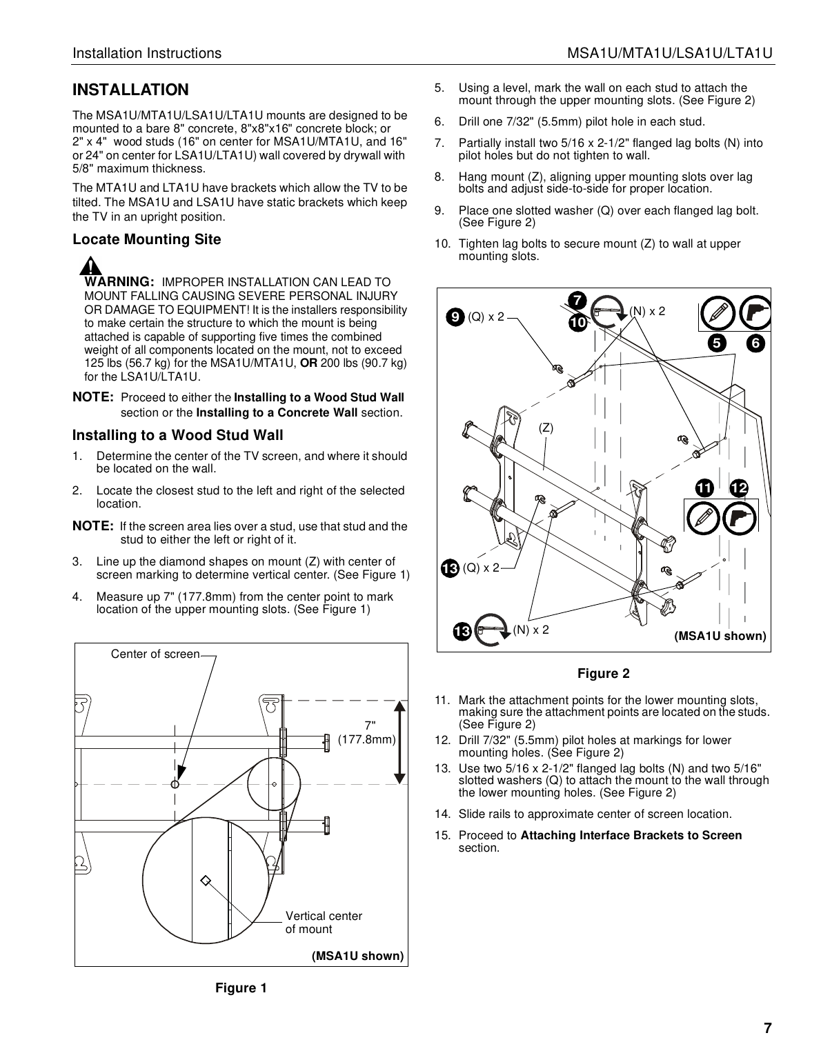
- Determine the TV's center location on the wall and identify the nearest studs (wood stud installs) or mark drill points (concrete installs).
- Line up the wall mount's diamond alignment marks with the screen's vertical center, then mark and drill for the upper mounting slots.
- Partially install lag bolts, hang the mount, adjust side-to-side, then fully tighten the upper mounting slots.
- Mark, drill, and secure the lower mounting slots the same way.
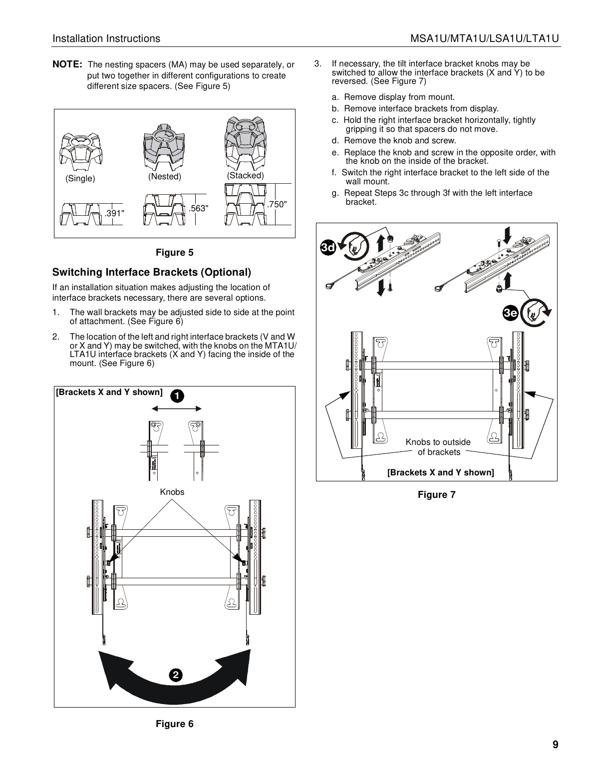
- Attach the interface brackets to the back of the screen, centered on the screen using the correct screws/spacers/washers for your display.
- Hang the screen onto the top rail of the wall mount, route cables, then pull the pull cords to latch the interface brackets and secure the bottom of the screen.
- Adjust horizontal position (up to 1" of play) and, on tilt models, set and lock the desired tilt angle (0°, 6°, or 12°).
- Optionally lock the screen interface brackets to the mount rails with set screws, and add a padlock (not included, max 5/16" shackle) to the interface bracket for extra security.
Installation Reference Diagrams
Tools Required
- #2 Phillips screwdriver
- 7/32" (5.5mm) drill bit for wood stud installs
- 3/8" (9.5mm) drill bit for concrete installs
- 3/16" x 10" bit (included) for reaching through deep mounting slots
A comprehensive universal hardware kit is included, covering M4–M8 screws, spacers, and washers for attaching brackets to a wide range of display models, plus a separate wall-mounting hardware kit (lag bolts, anchors, washers, and set screws) sized for wood stud or concrete walls.
Adjustments
- Horizontal: wall brackets adjust side-to-side up to 1" (25.4mm) at the point of attachment; the screen can also slide along the rails.
- Tilt (MTA1U/LTA1U only): loosen the interface bracket knob, adjust tilt, and lock at 0°, 6°, or 12° using the provided carriage bolt and hex nut, then retighten the knob.
Security Options (Optional)
- Lock the screen interface brackets onto the mount rails using a 3/8-16 x 3/4" set screw on each bracket.
- Add a padlock (not included, max 5/16"/7.9mm shackle diameter) to an interface bracket to secure the mount.